

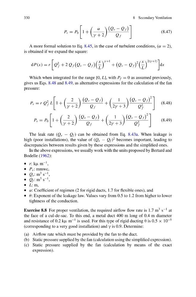
330
8 Secondary Ventilation
P v = P 0
1 +
α
γ + 2
Q v − Q f
Q f
(8.47)
A more formal solution to Eq. 8.45, in the case of turbulent conditions, (α = 2),
is obtained if we expand the square:
dP(x) = r
Q
2
f + 2 Q f
Q v − Q f
x
L
γ +1 +
Q v − Q f
2
x
L
2(γ +1)
dx
Which when integrated for the range [0, L], with P f = 0 as assumed previously,
gives us Eqs. 8.48 and 8.49, as alternative expressions for the calculation of the fan
pressure:
P v = r Q
2
f L
1 +
2
γ + 2
Q v − Q f
Q f
+
1
2γ + 3
Q v − Q f
2
Q
2
f
(8.48)
P v = P 0
1 +
2
γ + 2
Q v − Q f
Q f
+
1
2γ + 3
Q v − Q f
2
Q
2
f
(8.49)
The leak rate (Q v − Q f ) can be obtained from Eq. 8.43a. When leakage is
high (poor installations), the value of (Q v − Q f )
2 becomes important, leading to
discrepancies between results given by these expressions and the simplified ones.
In the above expressions, we usually work with the units proposed by Bertard and
Bodelle (1962):
• r: kμ m
−1 ,
• P v : mmwc,
• Q v : m
3 s
−1 ,
• Q f : m
3 s
−1 ,
• L: m,
• α: Coefficient of regimen (2 for rigid ducts, 1.7 for flexible ones), and
• θ: Exponent of the leakage law. Values vary from 0.5 to 1.2 from higher to lower
tightness of the conduction.
Exercise 8.8 For proper ventilation, the required airflow flow rate is 1.7 m
3 s
−1 at
the face of a cul-de-sac. To this end, a metal duct 400 m long of 0.4 m diameter
and resistance of 0.2 kμ m
−1 is used. For this type of rigid ducting θ is 0.5 × 10
−5
(corresponding to a very good installation) and γ is 0.9. Determine:
(a) Airflow rate which must be provided by the fan to the duct.
(b) Static pressure supplied by the fan (calculation using the simplified expression).
(c) Static pressure supplied by the fan (calculation by means of the exact
expression).
8 Secondary Ventilation
P v = P 0
1 +
α
γ + 2
Q v − Q f
Q f
(8.47)
A more formal solution to Eq. 8.45, in the case of turbulent conditions, (α = 2),
is obtained if we expand the square:
dP(x) = r
Q
2
f + 2 Q f
Q v − Q f
x
L
γ +1 +
Q v − Q f
2
x
L
2(γ +1)
dx
Which when integrated for the range [0, L], with P f = 0 as assumed previously,
gives us Eqs. 8.48 and 8.49, as alternative expressions for the calculation of the fan
pressure:
P v = r Q
2
f L
1 +
2
γ + 2
Q v − Q f
Q f
+
1
2γ + 3
Q v − Q f
2
Q
2
f
(8.48)
P v = P 0
1 +
2
γ + 2
Q v − Q f
Q f
+
1
2γ + 3
Q v − Q f
2
Q
2
f
(8.49)
The leak rate (Q v − Q f ) can be obtained from Eq. 8.43a. When leakage is
high (poor installations), the value of (Q v − Q f )
2 becomes important, leading to
discrepancies between results given by these expressions and the simplified ones.
In the above expressions, we usually work with the units proposed by Bertard and
Bodelle (1962):
• r: kμ m
−1 ,
• P v : mmwc,
• Q v : m
3 s
−1 ,
• Q f : m
3 s
−1 ,
• L: m,
• α: Coefficient of regimen (2 for rigid ducts, 1.7 for flexible ones), and
• θ: Exponent of the leakage law. Values vary from 0.5 to 1.2 from higher to lower
tightness of the conduction.
Exercise 8.8 For proper ventilation, the required airflow flow rate is 1.7 m
3 s
−1 at
the face of a cul-de-sac. To this end, a metal duct 400 m long of 0.4 m diameter
and resistance of 0.2 kμ m
−1 is used. For this type of rigid ducting θ is 0.5 × 10
−5
(corresponding to a very good installation) and γ is 0.9. Determine:
(a) Airflow rate which must be provided by the fan to the duct.
(b) Static pressure supplied by the fan (calculation using the simplified expression).
(c) Static pressure supplied by the fan (calculation by means of the exact
expression).