

8.13 Calculating Losses Along a Duct Using the Integral Method
327
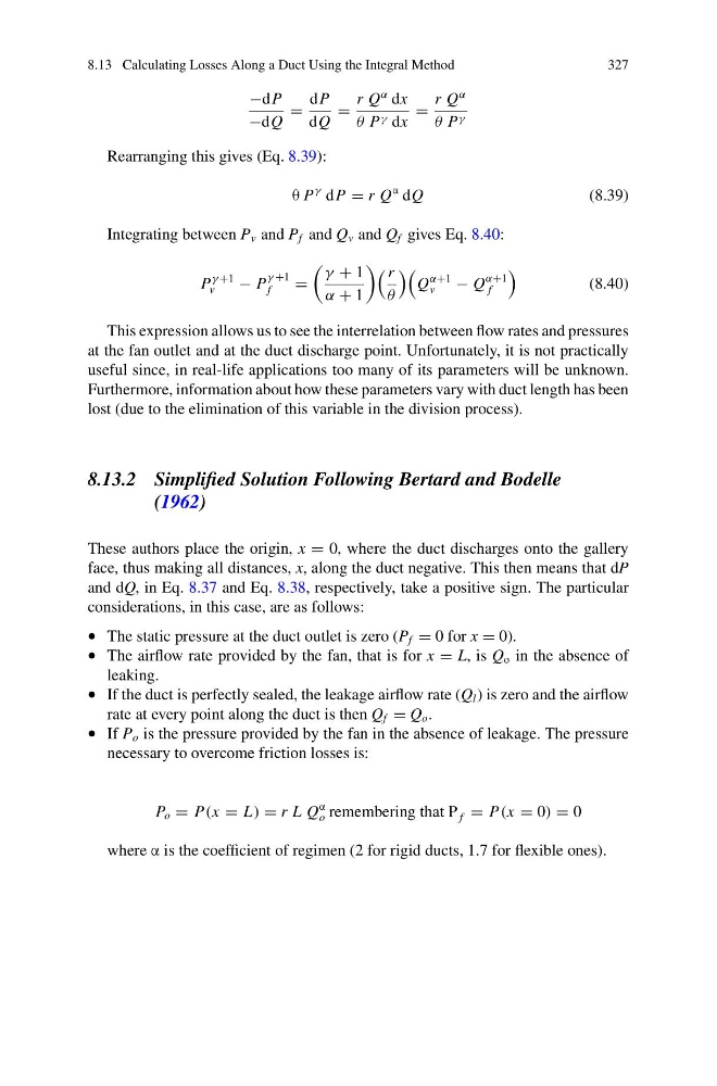
−dP
−dQ
=
dP
dQ
=
r Q
α dx
θ P γ dx
=
r Q
α
θ P γ
Rearranging this gives (Eq. 8.39):
θ P
γ dP = r Q
α dQ
(8.39)
Integrating between P v and P f and Q v and Q f gives Eq. 8.40:
P
γ +1
v
− P
γ +1
f
=
γ + 1
α + 1
r
θ
Q
α+1
v
− Q
α+1
f
(8.40)
This expression allows us to see the interrelation between flow rates and pressures
at the fan outlet and at the duct discharge point. Unfortunately, it is not practically
useful since, in real-life applications too many of its parameters will be unknown.
Furthermore, information about how these parameters vary with duct length has been
lost (due to the elimination of this variable in the division process).
8.13.2 Simplified Solution Following Bertard and Bodelle
(1962)
These authors place the origin, x = 0, where the duct discharges onto the gallery
face, thus making all distances, x, along the duct negative. This then means that dP
and dQ, in Eq. 8.37 and Eq. 8.38, respectively, take a positive sign. The particular
considerations, in this case, are as follows:
• The static pressure at the duct outlet is zero (P f = 0 for x = 0).
• The airflow rate provided by the fan, that is for x = L, is Q o in the absence of
leaking.
• If the duct is perfectly sealed, the leakage airflow rate (Q l ) is zero and the airflow
rate at every point along the duct is then Q f = Q o .
• If P o is the pressure provided by the fan in the absence of leakage. The pressure
necessary to overcome friction losses is:
P o = P(x = L) = r L Q
α
o remembering that P f = P(x = 0) = 0
where α is the coefficient of regimen (2 for rigid ducts, 1.7 for flexible ones).
327
−dP
−dQ
=
dP
dQ
=
r Q
α dx
θ P γ dx
=
r Q
α
θ P γ
Rearranging this gives (Eq. 8.39):
θ P
γ dP = r Q
α dQ
(8.39)
Integrating between P v and P f and Q v and Q f gives Eq. 8.40:
P
γ +1
v
− P
γ +1
f
=
γ + 1
α + 1
r
θ
Q
α+1
v
− Q
α+1
f
(8.40)
This expression allows us to see the interrelation between flow rates and pressures
at the fan outlet and at the duct discharge point. Unfortunately, it is not practically
useful since, in real-life applications too many of its parameters will be unknown.
Furthermore, information about how these parameters vary with duct length has been
lost (due to the elimination of this variable in the division process).
8.13.2 Simplified Solution Following Bertard and Bodelle
(1962)
These authors place the origin, x = 0, where the duct discharges onto the gallery
face, thus making all distances, x, along the duct negative. This then means that dP
and dQ, in Eq. 8.37 and Eq. 8.38, respectively, take a positive sign. The particular
considerations, in this case, are as follows:
• The static pressure at the duct outlet is zero (P f = 0 for x = 0).
• The airflow rate provided by the fan, that is for x = L, is Q o in the absence of
leaking.
• If the duct is perfectly sealed, the leakage airflow rate (Q l ) is zero and the airflow
rate at every point along the duct is then Q f = Q o .
• If P o is the pressure provided by the fan in the absence of leakage. The pressure
necessary to overcome friction losses is:
P o = P(x = L) = r L Q
α
o remembering that P f = P(x = 0) = 0
where α is the coefficient of regimen (2 for rigid ducts, 1.7 for flexible ones).