

326
8 Secondary Ventilation
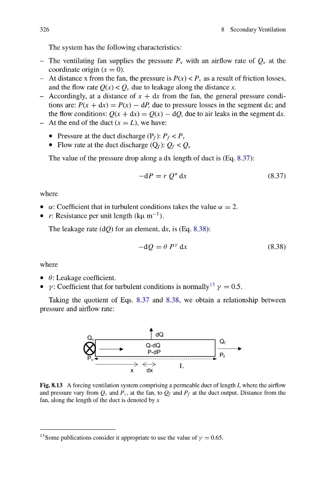
The system has the following characteristics:
– The ventilating fan supplies the pressure P v with an airflow rate of Q v at the
coordinate origin (x = 0).
– At distance x from the fan, the pressure is P(x) < P v as a result of friction losses,
and the flow rate Q(x) < Q v due to leakage along the distance x.
– Accordingly, at a distance of x + dx from the fan, the general pressure conditions are: P(x + dx) = P(x) − dP, due to pressure losses in the segment dx; and
the flow conditions: Q(x + dx) = Q(x) − dQ, due to air leaks in the segment dx.
– At the end of the duct (x = L), we have:
• Pressure at the duct discharge (P f ): P f < P v
• Flow rate at the duct discharge (Q f ): Q f < Q v
The value of the pressure drop along a dx length of duct is (Eq. 8.37):
−dP = r Q
α dx
(8.37)
where
• α: Coefficient that in turbulent conditions takes the value α = 2.
• r: Resistance per unit length (kμ m
−1
).
The leakage rate (dQ) for an element, dx, is (Eq. 8.38):
−dQ = θ P
γ dx
(8.38)
where
• θ: Leakage coefficient.
• γ : Coefficient that for turbulent conditions is normally
13
γ = 0.5.
Taking the quotient of Eqs. 8.37 and 8.38, we obtain a relationship between
pressure and airflow rate:
Q v
P v
Q f
P f
L
x
dx
dQ
Q-dQ
P-dP
Fig. 8.13 A forcing ventilation system comprising a permeable duct of length L where the airflow
and pressure vary from Q v and P v , at the fan, to Q f and P f at the duct output. Distance from the
fan, along the length of the duct is denoted by x
13 Some publications consider it appropriate to use the value of γ = 0.65.
8 Secondary Ventilation
The system has the following characteristics:
– The ventilating fan supplies the pressure P v with an airflow rate of Q v at the
coordinate origin (x = 0).
– At distance x from the fan, the pressure is P(x) < P v as a result of friction losses,
and the flow rate Q(x) < Q v due to leakage along the distance x.
– Accordingly, at a distance of x + dx from the fan, the general pressure conditions are: P(x + dx) = P(x) − dP, due to pressure losses in the segment dx; and
the flow conditions: Q(x + dx) = Q(x) − dQ, due to air leaks in the segment dx.
– At the end of the duct (x = L), we have:
• Pressure at the duct discharge (P f ): P f < P v
• Flow rate at the duct discharge (Q f ): Q f < Q v
The value of the pressure drop along a dx length of duct is (Eq. 8.37):
−dP = r Q
α dx
(8.37)
where
• α: Coefficient that in turbulent conditions takes the value α = 2.
• r: Resistance per unit length (kμ m
−1
).
The leakage rate (dQ) for an element, dx, is (Eq. 8.38):
−dQ = θ P
γ dx
(8.38)
where
• θ: Leakage coefficient.
• γ : Coefficient that for turbulent conditions is normally
13
γ = 0.5.
Taking the quotient of Eqs. 8.37 and 8.38, we obtain a relationship between
pressure and airflow rate:
Q v
P v
Q f
P f
L
x
dx
dQ
Q-dQ
P-dP
Fig. 8.13 A forcing ventilation system comprising a permeable duct of length L where the airflow
and pressure vary from Q v and P v , at the fan, to Q f and P f at the duct output. Distance from the
fan, along the length of the duct is denoted by x
13 Some publications consider it appropriate to use the value of γ = 0.65.