

322
8 Secondary Ventilation
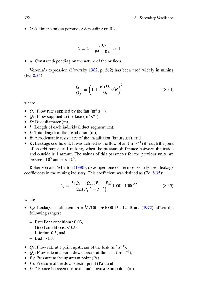
• λ: A dimensionless parameter depending on Re:
λ = 2 −
29.7
85 + Re
, and
• μ: Constant depending on the nature of the orifices.
Voronin’s expression (Novitzky 1962, p. 262) has been used widely in mining
(Eq. 8.34):
Q v
Q f
=
1 +
K DL
3l t
2
√
R
2
(8.34)
where
• Q v : Flow rate supplied by the fan (m
3 s
−1 ),
• Q f : Flow supplied to the face (m
3 s
−1 ),
• D: Duct diameter (m),
• l t : Length of each individual duct segment (m),
• L: Total length of the installation (m),
• R: Aerodynamic resistance of the installation (kmurgues), and
• K: Leakage coefficient. It was defined as the flow of air (m
3 s
−1 ) through the joint
of an arbitrary duct 1 m long, when the pressure difference between the inside
and outside is 1 mmwc. The values of this parameter for the previous units are
between 10
3 and 3 × 10
3 .
Robertson and Wharton (1980), developed one of the most widely used leakage
coefficients in the mining industry. This coefficient was defined as (Eq. 8.35):
L c =
3(Q 1 − Q 2 )(P 1 − P 2 )
2L
P
1.5
1 − P
1.5
2
1000 · 1000
0.5
(8.35)
where
• L c : Leakage coefficient in m
3 /s/100 m/1000 Pa. Le Roux (1972) offers the
following ranges:
– Excellent conditions: 0.03,
– Good conditions: <0.25,
– Inferior: 0.5, and
– Bad: >1.0.
• Q 1 : Flow rate at a point upstream of the leak (m
3 s
−1 ),
• Q 2 : Flow rate at a point downstream of the leak (m
3 s
−1 ),
• P 1 : Pressure at the upstream point (Pa),
• P 2 : Pressure at the downstream point (Pa), and
• L: Distance between upstream and downstream points (m).
8 Secondary Ventilation
• λ: A dimensionless parameter depending on Re:
λ = 2 −
29.7
85 + Re
, and
• μ: Constant depending on the nature of the orifices.
Voronin’s expression (Novitzky 1962, p. 262) has been used widely in mining
(Eq. 8.34):
Q v
Q f
=
1 +
K DL
3l t
2
√
R
2
(8.34)
where
• Q v : Flow rate supplied by the fan (m
3 s
−1 ),
• Q f : Flow supplied to the face (m
3 s
−1 ),
• D: Duct diameter (m),
• l t : Length of each individual duct segment (m),
• L: Total length of the installation (m),
• R: Aerodynamic resistance of the installation (kmurgues), and
• K: Leakage coefficient. It was defined as the flow of air (m
3 s
−1 ) through the joint
of an arbitrary duct 1 m long, when the pressure difference between the inside
and outside is 1 mmwc. The values of this parameter for the previous units are
between 10
3 and 3 × 10
3 .
Robertson and Wharton (1980), developed one of the most widely used leakage
coefficients in the mining industry. This coefficient was defined as (Eq. 8.35):
L c =
3(Q 1 − Q 2 )(P 1 − P 2 )
2L
P
1.5
1 − P
1.5
2
1000 · 1000
0.5
(8.35)
where
• L c : Leakage coefficient in m
3 /s/100 m/1000 Pa. Le Roux (1972) offers the
following ranges:
– Excellent conditions: 0.03,
– Good conditions: <0.25,
– Inferior: 0.5, and
– Bad: >1.0.
• Q 1 : Flow rate at a point upstream of the leak (m
3 s
−1 ),
• Q 2 : Flow rate at a point downstream of the leak (m
3 s
−1 ),
• P 1 : Pressure at the upstream point (Pa),
• P 2 : Pressure at the downstream point (Pa), and
• L: Distance between upstream and downstream points (m).