

8.12 Air Leaks in the Duct
321
• Q p : Loss in airflow rate (m
3 s
−1 ).
• A: Orifice area (m
2 ).
• ρ st : Standard air density (1.2 kg m
−3 ).
• ΔP: Static pressure difference between inside and outside the duct (Pa).
• n: A coefficient which approaches 1 for the laminar flow regime and varies between
0.5 and 1 for the turbulent flow regime. ASHRAE (2013) frequently uses n = 0.65.
• K: Dimensionless constant.
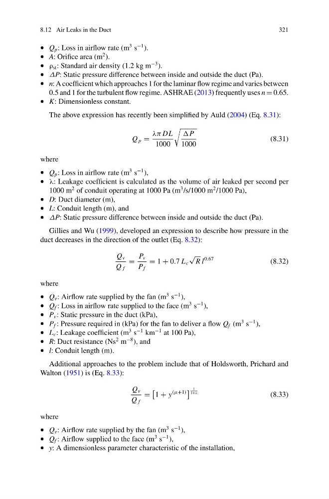
The above expression has recently been simplified by Auld (2004) (Eq. 8.31):
Q p =
λπ DL
1000
P
1000
(8.31)
where
• Q p : Loss in airflow rate (m
3 s
−1 ),
• λ: Leakage coefficient is calculated as the volume of air leaked per second per
1000 m
2 of conduit operating at 1000 Pa (m
3 /s/1000 m
2 /1000 Pa),
• D: Duct diameter (m),
• L: Conduit length (m), and
• ΔP: Static pressure difference between inside and outside the duct (Pa).
Gillies and Wu (1999), developed an expression to describe how pressure in the
duct decreases in the direction of the outlet (Eq. 8.32):
Q v
Q f
=
P v
P f
= 1 + 0.7 L c
√
R l
0.67
(8.32)
where
• Q v : Airflow rate supplied by the fan (m
3 s
−1 ),
• Q f : Loss in airflow rate supplied to the face (m
3 s
−1 ),
• P v : Static pressure in the duct (kPa),
• P f : Pressure required in (kPa) for the fan to deliver a flow Q f (m
3 s
−1 ),
• L c : Leakage coefficient (m
3 s
−1 km
−1 at 100 Pa),
• R: Duct resistance (Ns
2 m
−8 ), and
• l: Conduit length (m).
Additional approaches to the problem include that of Holdsworth, Prichard and
Walton (1951) is (Eq. 8.33):
Q v
Q f
=
1 + y
(μ+1)
1
1+λ
(8.33)
where
• Q v : Airflow rate supplied by the fan (m
3 s
−1 ),
• Q f : Airflow supplied to the face (m
3 s
−1 ),
• y: A dimensionless parameter characteristic of the installation,
321
• Q p : Loss in airflow rate (m
3 s
−1 ).
• A: Orifice area (m
2 ).
• ρ st : Standard air density (1.2 kg m
−3 ).
• ΔP: Static pressure difference between inside and outside the duct (Pa).
• n: A coefficient which approaches 1 for the laminar flow regime and varies between
0.5 and 1 for the turbulent flow regime. ASHRAE (2013) frequently uses n = 0.65.
• K: Dimensionless constant.
The above expression has recently been simplified by Auld (2004) (Eq. 8.31):
Q p =
λπ DL
1000
P
1000
(8.31)
where
• Q p : Loss in airflow rate (m
3 s
−1 ),
• λ: Leakage coefficient is calculated as the volume of air leaked per second per
1000 m
2 of conduit operating at 1000 Pa (m
3 /s/1000 m
2 /1000 Pa),
• D: Duct diameter (m),
• L: Conduit length (m), and
• ΔP: Static pressure difference between inside and outside the duct (Pa).
Gillies and Wu (1999), developed an expression to describe how pressure in the
duct decreases in the direction of the outlet (Eq. 8.32):
Q v
Q f
=
P v
P f
= 1 + 0.7 L c
√
R l
0.67
(8.32)
where
• Q v : Airflow rate supplied by the fan (m
3 s
−1 ),
• Q f : Loss in airflow rate supplied to the face (m
3 s
−1 ),
• P v : Static pressure in the duct (kPa),
• P f : Pressure required in (kPa) for the fan to deliver a flow Q f (m
3 s
−1 ),
• L c : Leakage coefficient (m
3 s
−1 km
−1 at 100 Pa),
• R: Duct resistance (Ns
2 m
−8 ), and
• l: Conduit length (m).
Additional approaches to the problem include that of Holdsworth, Prichard and
Walton (1951) is (Eq. 8.33):
Q v
Q f
=
1 + y
(μ+1)
1
1+λ
(8.33)
where
• Q v : Airflow rate supplied by the fan (m
3 s
−1 ),
• Q f : Airflow supplied to the face (m
3 s
−1 ),
• y: A dimensionless parameter characteristic of the installation,