

8.12 Air Leaks in the Duct
323
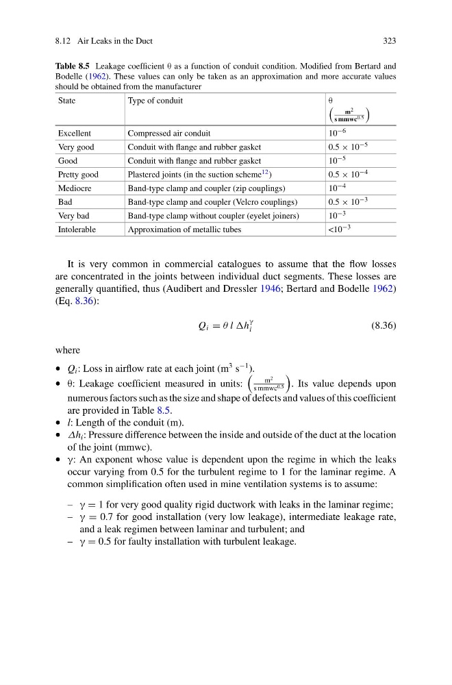
Table 8.5 Leakage coefficient θ as a function of conduit condition. Modified from Bertard and
Bodelle (1962). These values can only be taken as an approximation and more accurate values
should be obtained from the manufacturer
State
Type of conduit
θ
m 2
s mmwc 0.5
Excellent
Compressed air conduit
10 −6
Very good
Conduit with flange and rubber gasket
0.5 × 10 −5
Good
Conduit with flange and rubber gasket
10 −5
Pretty good
Plastered joints (in the suction scheme 12 )
0.5 × 10 −4
Mediocre
Band-type clamp and coupler (zip couplings)
10 −4
Bad
Band-type clamp and coupler (Velcro couplings)
0.5 × 10 −3
Very bad
Band-type clamp without coupler (eyelet joiners)
10 −3
Intolerable
Approximation of metallic tubes
<10 −3
It is very common in commercial catalogues to assume that the flow losses
are concentrated in the joints between individual duct segments. These losses are
generally quantified, thus (Audibert and Dressler 1946; Bertard and Bodelle 1962)
(Eq. 8.36):
Q i = θ l h
γ
i
(8.36)
where
• Q i : Loss in airflow rate at each joint (m
3 s
−1 ).
• θ: Leakage coefficient measured in units:
m
2
s mmwc 0.5
. Its value depends upon
numerous factors such as the size and shape of defects and values of this coefficient
are provided in Table 8.5.
• l: Length of the conduit (m).
• Δh i : Pressure difference between the inside and outside of the duct at the location
of the joint (mmwc).
• γ: An exponent whose value is dependent upon the regime in which the leaks
occur varying from 0.5 for the turbulent regime to 1 for the laminar regime. A
common simplification often used in mine ventilation systems is to assume:
– γ = 1 for very good quality rigid ductwork with leaks in the laminar regime;
– γ = 0.7 for good installation (very low leakage), intermediate leakage rate,
and a leak regimen between laminar and turbulent; and
– γ = 0.5 for faulty installation with turbulent leakage.
323
Table 8.5 Leakage coefficient θ as a function of conduit condition. Modified from Bertard and
Bodelle (1962). These values can only be taken as an approximation and more accurate values
should be obtained from the manufacturer
State
Type of conduit
θ
m 2
s mmwc 0.5
Excellent
Compressed air conduit
10 −6
Very good
Conduit with flange and rubber gasket
0.5 × 10 −5
Good
Conduit with flange and rubber gasket
10 −5
Pretty good
Plastered joints (in the suction scheme 12 )
0.5 × 10 −4
Mediocre
Band-type clamp and coupler (zip couplings)
10 −4
Bad
Band-type clamp and coupler (Velcro couplings)
0.5 × 10 −3
Very bad
Band-type clamp without coupler (eyelet joiners)
10 −3
Intolerable
Approximation of metallic tubes
<10 −3
It is very common in commercial catalogues to assume that the flow losses
are concentrated in the joints between individual duct segments. These losses are
generally quantified, thus (Audibert and Dressler 1946; Bertard and Bodelle 1962)
(Eq. 8.36):
Q i = θ l h
γ
i
(8.36)
where
• Q i : Loss in airflow rate at each joint (m
3 s
−1 ).
• θ: Leakage coefficient measured in units:
m
2
s mmwc 0.5
. Its value depends upon
numerous factors such as the size and shape of defects and values of this coefficient
are provided in Table 8.5.
• l: Length of the conduit (m).
• Δh i : Pressure difference between the inside and outside of the duct at the location
of the joint (mmwc).
• γ: An exponent whose value is dependent upon the regime in which the leaks
occur varying from 0.5 for the turbulent regime to 1 for the laminar regime. A
common simplification often used in mine ventilation systems is to assume:
– γ = 1 for very good quality rigid ductwork with leaks in the laminar regime;
– γ = 0.7 for good installation (very low leakage), intermediate leakage rate,
and a leak regimen between laminar and turbulent; and
– γ = 0.5 for faulty installation with turbulent leakage.