

20
1 Fundamental Concepts of Fluid Mechanics for Mine Ventilation
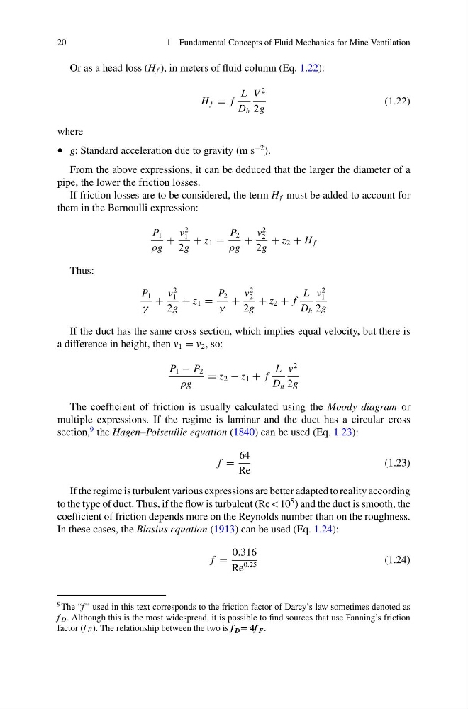
Or as a head loss (H f ), in meters of fluid column (Eq. 1.22):
H f = f
L
D h
V
2
2g
(1.22)
where
• g: Standard acceleration due to gravity (m s
−2 ).
From the above expressions, it can be deduced that the larger the diameter of a
pipe, the lower the friction losses.
If friction losses are to be considered, the term H f must be added to account for
them in the Bernoulli expression:
P 1
ρg
+
v
2
1
2g
+ z 1 =
P 2
ρg
+
v
2
2
2g
+ z 2 + H f
Thus:
P 1
γ
+
v
2
1
2g
+ z 1 =
P 2
γ
+
v
2
2
2g
+ z 2 + f
L
D h
v
2
1
2g
If the duct has the same cross section, which implies equal velocity, but there is
a difference in height, then v 1 = v 2 , so:
P 1 − P 2
ρg
= z 2 − z 1 + f
L
D h
v
2
2g
The coefficient of friction is usually calculated using the Moody diagram or
multiple expressions. If the regime is laminar and the duct has a circular cross
section,
9 the Hagen–Poiseuille equation (1840) can be used (Eq. 1.23):
f =
64
Re
(1.23)
If the regime is turbulent various expressions are better adapted to reality according
to the type of duct. Thus, if the flow is turbulent (Re < 10
5 ) and the duct is smooth, the
coefficient of friction depends more on the Reynolds number than on the roughness.
In these cases, the Blasius equation (1913) can be used (Eq. 1.24):
f =
0.316
Re
0.25
(1.24)
9 The “f ” used in this text corresponds to the friction factor of Darcy’s law sometimes denoted as
f D . Although this is the most widespread, it is possible to find sources that use Fanning’s friction
factor (f F ). The relationship between the two is f D = 4f F .
1 Fundamental Concepts of Fluid Mechanics for Mine Ventilation
Or as a head loss (H f ), in meters of fluid column (Eq. 1.22):
H f = f
L
D h
V
2
2g
(1.22)
where
• g: Standard acceleration due to gravity (m s
−2 ).
From the above expressions, it can be deduced that the larger the diameter of a
pipe, the lower the friction losses.
If friction losses are to be considered, the term H f must be added to account for
them in the Bernoulli expression:
P 1
ρg
+
v
2
1
2g
+ z 1 =
P 2
ρg
+
v
2
2
2g
+ z 2 + H f
Thus:
P 1
γ
+
v
2
1
2g
+ z 1 =
P 2
γ
+
v
2
2
2g
+ z 2 + f
L
D h
v
2
1
2g
If the duct has the same cross section, which implies equal velocity, but there is
a difference in height, then v 1 = v 2 , so:
P 1 − P 2
ρg
= z 2 − z 1 + f
L
D h
v
2
2g
The coefficient of friction is usually calculated using the Moody diagram or
multiple expressions. If the regime is laminar and the duct has a circular cross
section,
9 the Hagen–Poiseuille equation (1840) can be used (Eq. 1.23):
f =
64
Re
(1.23)
If the regime is turbulent various expressions are better adapted to reality according
to the type of duct. Thus, if the flow is turbulent (Re < 10
5 ) and the duct is smooth, the
coefficient of friction depends more on the Reynolds number than on the roughness.
In these cases, the Blasius equation (1913) can be used (Eq. 1.24):
f =
0.316
Re
0.25
(1.24)
9 The “f ” used in this text corresponds to the friction factor of Darcy’s law sometimes denoted as
f D . Although this is the most widespread, it is possible to find sources that use Fanning’s friction
factor (f F ). The relationship between the two is f D = 4f F .