

6.4 Calculation by the Simplified Expression of the Regulator Area
241
Finally, the area of the regulator can be estimated by applying Eq. 6.24:
A =
1.2
√
Q
1.2
√
6611.63 Pa
· 45
m
3
s
= 0.66 m
2
6.5 Precise Calculation of the Regulator Area
At present, formulations that are more precise than the preceding one tend to be
used (e.g. Kingery 1960; Hartman 2012). In order to define them, one can start
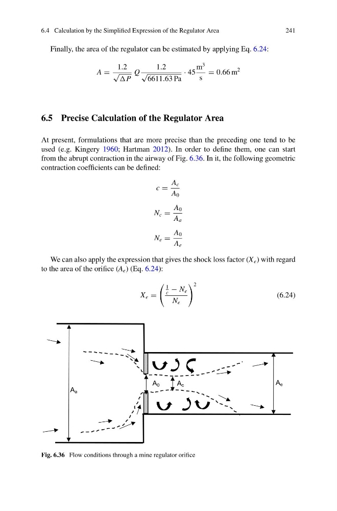
from the abrupt contraction in the airway of Fig. 6.36. In it, the following geometric
contraction coefficients can be defined:
c =
A c
A 0
N c =
A 0
A a
N e =
A 0
A e
We can also apply the expression that gives the shock loss factor (X e ) with regard
to the area of the orifice (A e ) (Eq. 6.24):
X e =
1
c
− N e
N e
2
(6.24)
A a
A 0
A c
A e
Fig. 6.36 Flow conditions through a mine regulator orifice
241
Finally, the area of the regulator can be estimated by applying Eq. 6.24:
A =
1.2
√
Q
1.2
√
6611.63 Pa
· 45
m
3
s
= 0.66 m
2
6.5 Precise Calculation of the Regulator Area
At present, formulations that are more precise than the preceding one tend to be
used (e.g. Kingery 1960; Hartman 2012). In order to define them, one can start
from the abrupt contraction in the airway of Fig. 6.36. In it, the following geometric
contraction coefficients can be defined:
c =
A c
A 0
N c =
A 0
A a
N e =
A 0
A e
We can also apply the expression that gives the shock loss factor (X e ) with regard
to the area of the orifice (A e ) (Eq. 6.24):
X e =
1
c
− N e
N e
2
(6.24)
A a
A 0
A c
A e
Fig. 6.36 Flow conditions through a mine regulator orifice