

242
6 Fans and Flow Control Devices
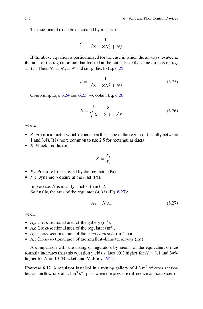
The coefficient c can be calculated by means of:
c =
1
Z − Z N 2
c + N 2
e
If the above equation is particularized for the case in which the airways located at
the inlet of the regulator and that located at the outlet have the same dimension (A a
= A e ). Then, N c = N e = N and simplifies to Eq. 6.25:
c =
1
√
Z − Z N 2 + N 2
(6.25)
Combining Eqs. 6.24 and 6.25, we obtain Eq. 6.26:
N =
Z
X + Z + 2
√
X
(6.26)
where
• Z: Empirical factor which depends on the shape of the regulator (usually between
1 and 3.8). It is more common to use 2.5 for rectangular ducts.
• X: Shock loss factor,
X =
P x
P v
.
• P x : Pressure loss caussed by the regulator (Pa).
• P v : Dynamic pressure at the inlet (Pa).
In practice, N is usually smaller than 0.2.
So finally, the area of the regulator (A 0 ) is (Eq. 6.27):
A 0 = N A a
(6.27)
where
• A a : Cross-sectional area of the gallery (m
2 ),
• A 0 : Cross-sectional area of the regulator (m
2 ),
• A c : Cross-sectional area of the vena contracta (m
2 ), and
• A e : Cross-sectional area of the smallest-diameter airway (m
2 ).
A comparison with the sizing of regulators by means of the equivalent orifice
formula indicates that this equation yields values 10% higher for N = 0.1 and 30%
higher for N = 0.3 (Brackett and McElroy 1941).
Exercise 6.12 A regulator installed in a mining gallery of 4.3 m
2 of cross section
lets an airflow rate of 4.1 m
3 s
−1 pass when the pressure difference on both sides of
6 Fans and Flow Control Devices
The coefficient c can be calculated by means of:
c =
1
Z − Z N 2
c + N 2
e
If the above equation is particularized for the case in which the airways located at
the inlet of the regulator and that located at the outlet have the same dimension (A a
= A e ). Then, N c = N e = N and simplifies to Eq. 6.25:
c =
1
√
Z − Z N 2 + N 2
(6.25)
Combining Eqs. 6.24 and 6.25, we obtain Eq. 6.26:
N =
Z
X + Z + 2
√
X
(6.26)
where
• Z: Empirical factor which depends on the shape of the regulator (usually between
1 and 3.8). It is more common to use 2.5 for rectangular ducts.
• X: Shock loss factor,
X =
P x
P v
.
• P x : Pressure loss caussed by the regulator (Pa).
• P v : Dynamic pressure at the inlet (Pa).
In practice, N is usually smaller than 0.2.
So finally, the area of the regulator (A 0 ) is (Eq. 6.27):
A 0 = N A a
(6.27)
where
• A a : Cross-sectional area of the gallery (m
2 ),
• A 0 : Cross-sectional area of the regulator (m
2 ),
• A c : Cross-sectional area of the vena contracta (m
2 ), and
• A e : Cross-sectional area of the smallest-diameter airway (m
2 ).
A comparison with the sizing of regulators by means of the equivalent orifice
formula indicates that this equation yields values 10% higher for N = 0.1 and 30%
higher for N = 0.3 (Brackett and McElroy 1941).
Exercise 6.12 A regulator installed in a mining gallery of 4.3 m
2 of cross section
lets an airflow rate of 4.1 m
3 s
−1 pass when the pressure difference on both sides of