

222
6 Fans and Flow Control Devices
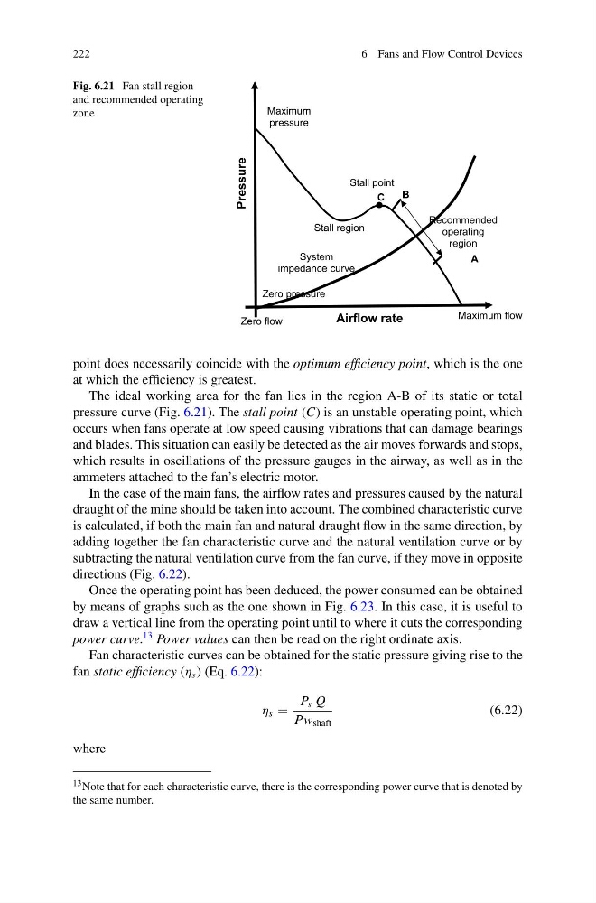
Fig. 6.21 Fan stall region
and recommended operating
zone
Airflow rate
Zero flow
Maximum flow
System
impedance curve
Stall point
Stall region
Recommended
operating
region
A
B
C
Maximum
pressure
Zero pressure
Pressure
point does necessarily coincide with the optimum efficiency point, which is the one
at which the efficiency is greatest.
The ideal working area for the fan lies in the region A-B of its static or total
pressure curve (Fig. 6.21). The stall point (C) is an unstable operating point, which
occurs when fans operate at low speed causing vibrations that can damage bearings
and blades. This situation can easily be detected as the air moves forwards and stops,
which results in oscillations of the pressure gauges in the airway, as well as in the
ammeters attached to the fan’s electric motor.
In the case of the main fans, the airflow rates and pressures caused by the natural
draught of the mine should be taken into account. The combined characteristic curve
is calculated, if both the main fan and natural draught flow in the same direction, by
adding together the fan characteristic curve and the natural ventilation curve or by
subtracting the natural ventilation curve from the fan curve, if they move in opposite
directions (Fig. 6.22).
Once the operating point has been deduced, the power consumed can be obtained
by means of graphs such as the one shown in Fig. 6.23. In this case, it is useful to
draw a vertical line from the operating point until to where it cuts the corresponding
power curve.
13 Power values can then be read on the right ordinate axis.
Fan characteristic curves can be obtained for the static pressure giving rise to the
fan static efficiency (η s ) (Eq. 6.22):
η s =
P s Q
Pw shaft
(6.22)
where
13 Note that for each characteristic curve, there is the corresponding power curve that is denoted by
the same number.
6 Fans and Flow Control Devices
Fig. 6.21 Fan stall region
and recommended operating
zone
Airflow rate
Zero flow
Maximum flow
System
impedance curve
Stall point
Stall region
Recommended
operating
region
A
B
C
Maximum
pressure
Zero pressure
Pressure
point does necessarily coincide with the optimum efficiency point, which is the one
at which the efficiency is greatest.
The ideal working area for the fan lies in the region A-B of its static or total
pressure curve (Fig. 6.21). The stall point (C) is an unstable operating point, which
occurs when fans operate at low speed causing vibrations that can damage bearings
and blades. This situation can easily be detected as the air moves forwards and stops,
which results in oscillations of the pressure gauges in the airway, as well as in the
ammeters attached to the fan’s electric motor.
In the case of the main fans, the airflow rates and pressures caused by the natural
draught of the mine should be taken into account. The combined characteristic curve
is calculated, if both the main fan and natural draught flow in the same direction, by
adding together the fan characteristic curve and the natural ventilation curve or by
subtracting the natural ventilation curve from the fan curve, if they move in opposite
directions (Fig. 6.22).
Once the operating point has been deduced, the power consumed can be obtained
by means of graphs such as the one shown in Fig. 6.23. In this case, it is useful to
draw a vertical line from the operating point until to where it cuts the corresponding
power curve.
13 Power values can then be read on the right ordinate axis.
Fan characteristic curves can be obtained for the static pressure giving rise to the
fan static efficiency (η s ) (Eq. 6.22):
η s =
P s Q
Pw shaft
(6.22)
where
13 Note that for each characteristic curve, there is the corresponding power curve that is denoted by
the same number.