

6.2 Fans
221
Pressure
Airflow rate
Fan curve
Blocked
Limited
Open
Test rig
Free delivery
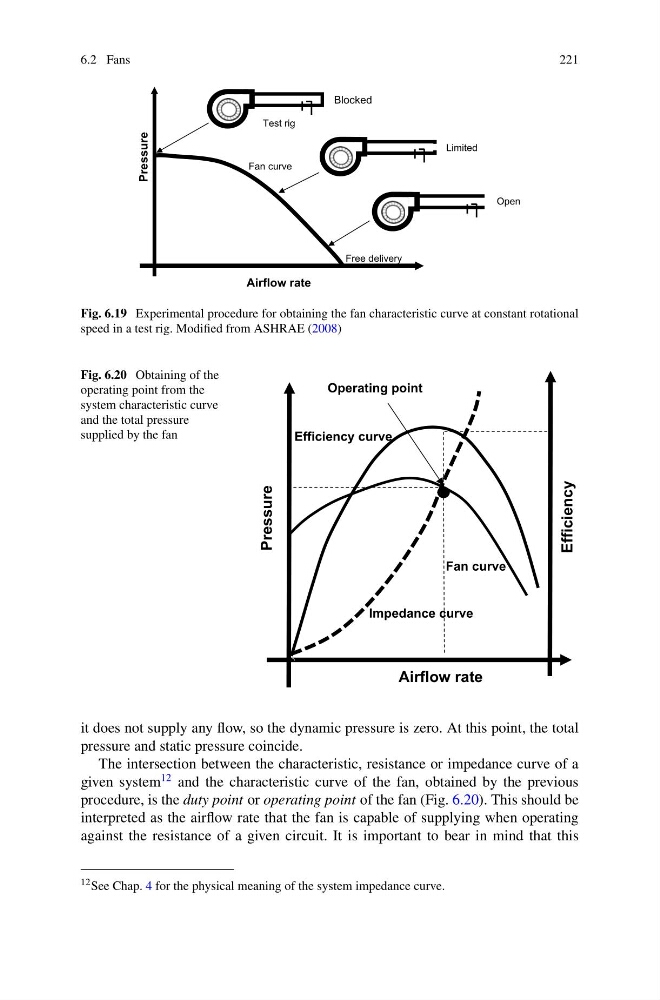
Fig. 6.19 Experimental procedure for obtaining the fan characteristic curve at constant rotational
speed in a test rig. Modified from ASHRAE (2008)
Fig. 6.20 Obtaining of the
operating point from the
system characteristic curve
and the total pressure
supplied by the fan
Impedance curve
Fan curve
Efficiency curve
Operating point
Airflow rate
Pressure
Efficiency
it does not supply any flow, so the dynamic pressure is zero. At this point, the total
pressure and static pressure coincide.
The intersection between the characteristic, resistance or impedance curve of a
given system
12 and the characteristic curve of the fan, obtained by the previous
procedure, is the duty point or operating point of the fan (Fig. 6.20). This should be
interpreted as the airflow rate that the fan is capable of supplying when operating
against the resistance of a given circuit. It is important to bear in mind that this
12 See Chap. 4 for the physical meaning of the system impedance curve.
221
Pressure
Airflow rate
Fan curve
Blocked
Limited
Open
Test rig
Free delivery
Fig. 6.19 Experimental procedure for obtaining the fan characteristic curve at constant rotational
speed in a test rig. Modified from ASHRAE (2008)
Fig. 6.20 Obtaining of the
operating point from the
system characteristic curve
and the total pressure
supplied by the fan
Impedance curve
Fan curve
Efficiency curve
Operating point
Airflow rate
Pressure
Efficiency
it does not supply any flow, so the dynamic pressure is zero. At this point, the total
pressure and static pressure coincide.
The intersection between the characteristic, resistance or impedance curve of a
given system
12 and the characteristic curve of the fan, obtained by the previous
procedure, is the duty point or operating point of the fan (Fig. 6.20). This should be
interpreted as the airflow rate that the fan is capable of supplying when operating
against the resistance of a given circuit. It is important to bear in mind that this
12 See Chap. 4 for the physical meaning of the system impedance curve.