

4.10 Complex Networks
135
Entering the appropriate values into the resulting equation and imposing the
condition Q 12 ≤ Q e = 150, the solution is obtained:
Mesh 1
Mesh 2
M 1 + M 2
f (solver):
−3216.83
3216.83
0.00
Q 12
68.80
Observe that the result we find here is equal to that obtained using the same method
but considering airflow directions as shown in Fig. 1. Once Q 12 is obtained, the rest
of the airflow rates can be calculated directly through the relations obtained using
Kirchhoff’s first law for the nodes.
Conclusion: The appearance of negative airflow rates implies that the direction
initially assigned to the flow is not correct. Indeed, even the absolute value of the
solution obtained cannot be trusted. To be sure that the correct values have been
found, all results obtained must be positive. For this reason, when a negative value is
obtained, the direction of airflow circulation should be reversed and the calculations
must be repeated. Only when the validity of a solution for the airflow rate has been
checked can other parameters be calculated.
(c) Calculation of the pressure supplied by the fan in branch 2–4.
P v = 3 216.8 Pa (calculated with mesh M 1 equation).
(d) Characteristics of the fan required in branch R 24 .
Bearing in mind that Q 24 = 50 m
3 s
−1 and P v = 3 216.8 Pa, the useful power is
Pw = 3 216.8 Pa · 50 m
3 s
−1
= 160.8 kW
(e) Total power of the ventilation system.
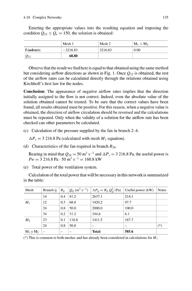
Calculation of the total power that will be necessary in this network is summarized
in the table:
Mesh
Branch ij R ij Q ij (m 3 s −1 ) P ij = R ij Q 2
ij (Pa) Useful power (kW) Notes
14
0.4 81.2
2637.1
214.1
M 1
12
0.3 68.8
1420.2
97.7
24
0.8 50.0
2000.0
100.0
34
0.2 31.2
194.6
6.1
M 2
23
0.1 118.8
1411.5
167.7
24
0.8 50.0
–
–
(*)
M 1 y M 2 –
–
–
Total:
585.6
(*) This is common to both meshes and has already been considered in calculations for M 1
135
Entering the appropriate values into the resulting equation and imposing the
condition Q 12 ≤ Q e = 150, the solution is obtained:
Mesh 1
Mesh 2
M 1 + M 2
f (solver):
−3216.83
3216.83
0.00
Q 12
68.80
Observe that the result we find here is equal to that obtained using the same method
but considering airflow directions as shown in Fig. 1. Once Q 12 is obtained, the rest
of the airflow rates can be calculated directly through the relations obtained using
Kirchhoff’s first law for the nodes.
Conclusion: The appearance of negative airflow rates implies that the direction
initially assigned to the flow is not correct. Indeed, even the absolute value of the
solution obtained cannot be trusted. To be sure that the correct values have been
found, all results obtained must be positive. For this reason, when a negative value is
obtained, the direction of airflow circulation should be reversed and the calculations
must be repeated. Only when the validity of a solution for the airflow rate has been
checked can other parameters be calculated.
(c) Calculation of the pressure supplied by the fan in branch 2–4.
P v = 3 216.8 Pa (calculated with mesh M 1 equation).
(d) Characteristics of the fan required in branch R 24 .
Bearing in mind that Q 24 = 50 m
3 s
−1 and P v = 3 216.8 Pa, the useful power is
Pw = 3 216.8 Pa · 50 m
3 s
−1
= 160.8 kW
(e) Total power of the ventilation system.
Calculation of the total power that will be necessary in this network is summarized
in the table:
Mesh
Branch ij R ij Q ij (m 3 s −1 ) P ij = R ij Q 2
ij (Pa) Useful power (kW) Notes
14
0.4 81.2
2637.1
214.1
M 1
12
0.3 68.8
1420.2
97.7
24
0.8 50.0
2000.0
100.0
34
0.2 31.2
194.6
6.1
M 2
23
0.1 118.8
1411.5
167.7
24
0.8 50.0
–
–
(*)
M 1 y M 2 –
–
–
Total:
585.6
(*) This is common to both meshes and has already been considered in calculations for M 1