

134
4 Mine Ventilation Networks
Mesh M 1
Branch
Pressure drop
Fan
Q 12
0.3 Q 2
12
No
Q 24
−0.8 · 50 2
+P v
Q 14
−0.4 (150 − Q 12 ) 2
No
Mesh M 1
H ij = 0
−0.1 Q 2
12 + 120 Q 12 − 11000 + P v = 0
Mesh M 2
Branch
Pressure drop
Fan
N 2 − N 3
0.1 (Q 12 + 50) 2
No
N 3 − N 4
−0.2 (100 − Q 12 ) 2
No
N 4 − N 2
0.8·50 2
−P v
Mesh M 2
H ij = 0
−0.1 Q 2
12 + 50 Q 12 + 250 − P v = 0
Mesh M 1 : −0.1 Q
2
12 + 120 Q 12 – 11000 + P v = 0
Mesh M 2 : −0.1 Q
2
12 +50 Q 12 + 250 − P v = 0
-----------------------------------------M 1 + M 2 : +0.2 Q
2
12 + 170 Q 12 − 10750 = 0
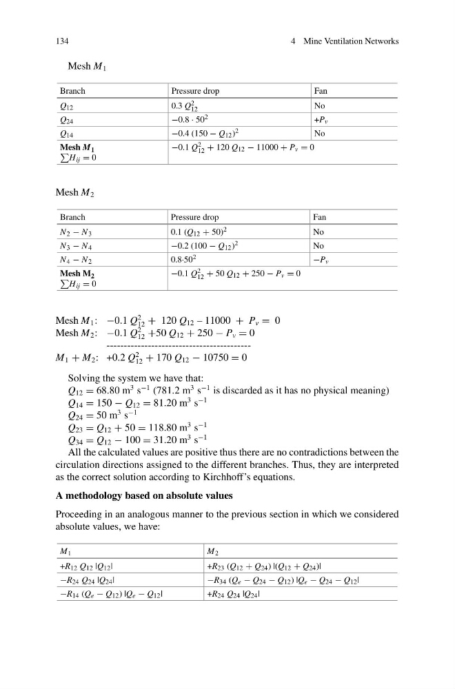
Solving the system we have that:
Q 12 = 68.80 m
3 s
−1 (781.2 m
3 s
−1 is discarded as it has no physical meaning)
Q 14 = 150 − Q 12 = 81.20 m
3 s
−1
Q 24 = 50 m
3 s
−1
Q 23 = Q 12 + 50 = 118.80 m
3 s
−1
Q 34 = Q 12 − 100 = 31.20 m
3 s
−1
All the calculated values are positive thus there are no contradictions between the
circulation directions assigned to the different branches. Thus, they are interpreted
as the correct solution according to Kirchhoff’s equations.
A methodology based on absolute values
Proceeding in an analogous manner to the previous section in which we considered
absolute values, we have:
M 1
M 2
+R 12 Q 12 |Q 12 |
+R 23 (Q 12 + Q 24 ) |(Q 12 + Q 24 )|
−R 24 Q 24 |Q 24 |
−R 34 (Q e − Q 24 − Q 12 ) |Q e − Q 24 − Q 12 |
−R 14 (Q e − Q 12 ) |Q e − Q 12 |
+R 24 Q 24 |Q 24 |
4 Mine Ventilation Networks
Mesh M 1
Branch
Pressure drop
Fan
Q 12
0.3 Q 2
12
No
Q 24
−0.8 · 50 2
+P v
Q 14
−0.4 (150 − Q 12 ) 2
No
Mesh M 1
H ij = 0
−0.1 Q 2
12 + 120 Q 12 − 11000 + P v = 0
Mesh M 2
Branch
Pressure drop
Fan
N 2 − N 3
0.1 (Q 12 + 50) 2
No
N 3 − N 4
−0.2 (100 − Q 12 ) 2
No
N 4 − N 2
0.8·50 2
−P v
Mesh M 2
H ij = 0
−0.1 Q 2
12 + 50 Q 12 + 250 − P v = 0
Mesh M 1 : −0.1 Q
2
12 + 120 Q 12 – 11000 + P v = 0
Mesh M 2 : −0.1 Q
2
12 +50 Q 12 + 250 − P v = 0
-----------------------------------------M 1 + M 2 : +0.2 Q
2
12 + 170 Q 12 − 10750 = 0
Solving the system we have that:
Q 12 = 68.80 m
3 s
−1 (781.2 m
3 s
−1 is discarded as it has no physical meaning)
Q 14 = 150 − Q 12 = 81.20 m
3 s
−1
Q 24 = 50 m
3 s
−1
Q 23 = Q 12 + 50 = 118.80 m
3 s
−1
Q 34 = Q 12 − 100 = 31.20 m
3 s
−1
All the calculated values are positive thus there are no contradictions between the
circulation directions assigned to the different branches. Thus, they are interpreted
as the correct solution according to Kirchhoff’s equations.
A methodology based on absolute values
Proceeding in an analogous manner to the previous section in which we considered
absolute values, we have:
M 1
M 2
+R 12 Q 12 |Q 12 |
+R 23 (Q 12 + Q 24 ) |(Q 12 + Q 24 )|
−R 24 Q 24 |Q 24 |
−R 34 (Q e − Q 24 − Q 12 ) |Q e − Q 24 − Q 12 |
−R 14 (Q e − Q 12 ) |Q e − Q 12 |
+R 24 Q 24 |Q 24 |