

4.10 Complex Networks
133
It can be observed that, by making the problem independent of the selection of
a correct initial direction of circulation, the solution obtained, Q 12 = 68.80, differs
only slightly from the value of Q 12 = 65.47 found using the previous method.
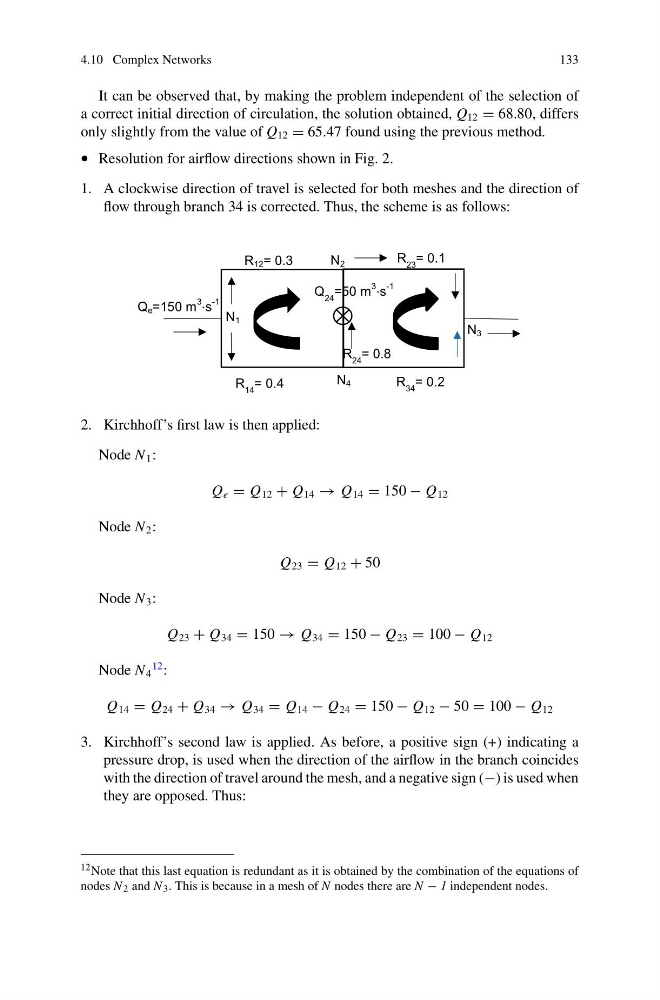
• Resolution for airflow directions shown in Fig. 2.
1. A clockwise direction of travel is selected for both meshes and the direction of
flow through branch 34 is corrected. Thus, the scheme is as follows:
N 1
N 2
N 4
N 3
Q e =150 m
3
⋅s
-1
R 12 = 0.3
R 14 = 0.4
R 23 = 0.1
R 34 = 0.2
R 24 = 0.8
Q 24 =50 m
3
⋅s
-1
2. Kirchhoff’s first law is then applied:
Node N 1 :
Q e = Q 12 + Q 14 → Q 14 = 150 − Q 12
Node N 2 :
Q 23 = Q 12 + 50
Node N 3 :
Q 23 + Q 34 = 150 → Q 34 = 150 − Q 23 = 100 − Q 12
Node N 4
12 :
Q 14 = Q 24 + Q 34 → Q 34 = Q 14 − Q 24 = 150 − Q 12 − 50 = 100 − Q 12
3. Kirchhoff’s second law is applied. As before, a positive sign (+) indicating a
pressure drop, is used when the direction of the airflow in the branch coincides
with the direction of travel around the mesh, and a negative sign (−) is used when
they are opposed. Thus:
12 Note that this last equation is redundant as it is obtained by the combination of the equations of
nodes N 2 and N 3 . This is because in a mesh of N nodes there are N − 1 independent nodes.
133
It can be observed that, by making the problem independent of the selection of
a correct initial direction of circulation, the solution obtained, Q 12 = 68.80, differs
only slightly from the value of Q 12 = 65.47 found using the previous method.
• Resolution for airflow directions shown in Fig. 2.
1. A clockwise direction of travel is selected for both meshes and the direction of
flow through branch 34 is corrected. Thus, the scheme is as follows:
N 1
N 2
N 4
N 3
Q e =150 m
3
⋅s
-1
R 12 = 0.3
R 14 = 0.4
R 23 = 0.1
R 34 = 0.2
R 24 = 0.8
Q 24 =50 m
3
⋅s
-1
2. Kirchhoff’s first law is then applied:
Node N 1 :
Q e = Q 12 + Q 14 → Q 14 = 150 − Q 12
Node N 2 :
Q 23 = Q 12 + 50
Node N 3 :
Q 23 + Q 34 = 150 → Q 34 = 150 − Q 23 = 100 − Q 12
Node N 4
12 :
Q 14 = Q 24 + Q 34 → Q 34 = Q 14 − Q 24 = 150 − Q 12 − 50 = 100 − Q 12
3. Kirchhoff’s second law is applied. As before, a positive sign (+) indicating a
pressure drop, is used when the direction of the airflow in the branch coincides
with the direction of travel around the mesh, and a negative sign (−) is used when
they are opposed. Thus:
12 Note that this last equation is redundant as it is obtained by the combination of the equations of
nodes N 2 and N 3 . This is because in a mesh of N nodes there are N − 1 independent nodes.