

37
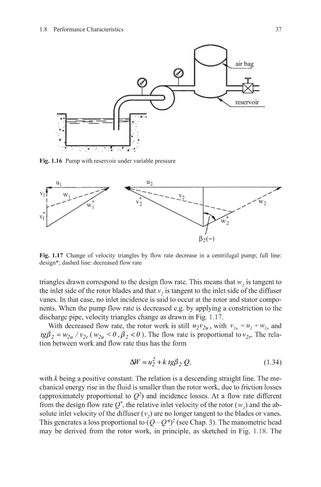
triangles drawn correspond to the design flow rate. This means that w 1 is tangent to
the inlet side of the rotor blades and that v 2 is tangent to the inlet side of the diffuser
vanes. In that case, no inlet incidence is said to occur at the rotor and stator components. When the pump flow rate is decreased e.g. by applying a constriction to the
discharge pipe, velocity triangles change as drawn in Fig. 1.17.
With decreased flow rate, the rotor work is still 2 2u
u v , with v
u w
u
u
2 = +
2
2 and
2
2u
2r
tg
w / v
b =
(
<
2u
w
0, 2 0
b < ). The flow rate is proportional to 2r
v . The relation between work and flow rate thus has the form
(1.34)
with k being a positive constant. The relation is a descending straight line. The mechanical energy rise in the fluid is smaller than the rotor work, due to friction losses
(approximately proportional to Q
2
) and incidence losses. At a flow rate different
from the design flow rate Q
*
, the relative inlet velocity of the rotor ( w 1 ) and the absolute inlet velocity of the diffuser ( v 2 ) are no longer tangent to the blades or vanes.
This generates a loss proportional to ( Q—Q*)
2
(see Chap. 3). The manometric head
may be derived from the rotor work, in principle, as sketched in Fig. 1.18. The
2
2
2
W u k tg Q,
D
b
= +
1.8 Performance Characteristics
Fig. 1.16 Pump with reservoir under variable pressure
1
u
1
v
*
1
v
1
w
*
1
w
2
u
*
2
v
2
v
2
w
*
2
w
)
(
2 −
β
Fig. 1.17 Change of velocity triangles by flow rate decrease in a centrifugal pump; full line:
design*; dashed line: decreased flow rate
triangles drawn correspond to the design flow rate. This means that w 1 is tangent to
the inlet side of the rotor blades and that v 2 is tangent to the inlet side of the diffuser
vanes. In that case, no inlet incidence is said to occur at the rotor and stator components. When the pump flow rate is decreased e.g. by applying a constriction to the
discharge pipe, velocity triangles change as drawn in Fig. 1.17.
With decreased flow rate, the rotor work is still 2 2u
u v , with v
u w
u
u
2 = +
2
2 and
2
2u
2r
tg
w / v
b =
(
<
2u
w
0, 2 0
b < ). The flow rate is proportional to 2r
v . The relation between work and flow rate thus has the form
(1.34)
with k being a positive constant. The relation is a descending straight line. The mechanical energy rise in the fluid is smaller than the rotor work, due to friction losses
(approximately proportional to Q
2
) and incidence losses. At a flow rate different
from the design flow rate Q
*
, the relative inlet velocity of the rotor ( w 1 ) and the absolute inlet velocity of the diffuser ( v 2 ) are no longer tangent to the blades or vanes.
This generates a loss proportional to ( Q—Q*)
2
(see Chap. 3). The manometric head
may be derived from the rotor work, in principle, as sketched in Fig. 1.18. The
2
2
2
W u k tg Q,
D
b
= +
1.8 Performance Characteristics
Fig. 1.16 Pump with reservoir under variable pressure
1
u
1
v
*
1
v
1
w
*
1
w
2
u
*
2
v
2
v
2
w
*
2
w
)
(
2 −
β
Fig. 1.17 Change of velocity triangles by flow rate decrease in a centrifugal pump; full line:
design*; dashed line: decreased flow rate