

35
1.7 Examples of Radial Turbomachines
lies in the turbine sense. To make the lift term less negative, the blades at the rotor
outlet should be leaning less far backward. With a meridional velocity component,
as drawn, this implies that diffusion then has to be built in ( w 2 < w 1 ). It is impossible
however to achieve strong deceleration in a diverging channel of limited length. As
will be discussed in Chap. 2, a velocity ratio amounting to about 0.7 may be reached
within optimal, stationary diffusers of limited length, i.e. about half of the kinetic
energy at the inlet may be converted into pressure energy. Due to disadvantageous
channel shapes within rotors, to strong changes of the shape of the cross-section and
to rotation effects, the velocity ratio w 2 /w 1 cannot be less than about 0.8–0.9; with as
a consequence that lift cannot intervene in the pump sense. The functioning is thus
essentially based on Coriolis force. The rotor has to be considered as consisting of
rotating channels. The blades do not function as lifting objects.
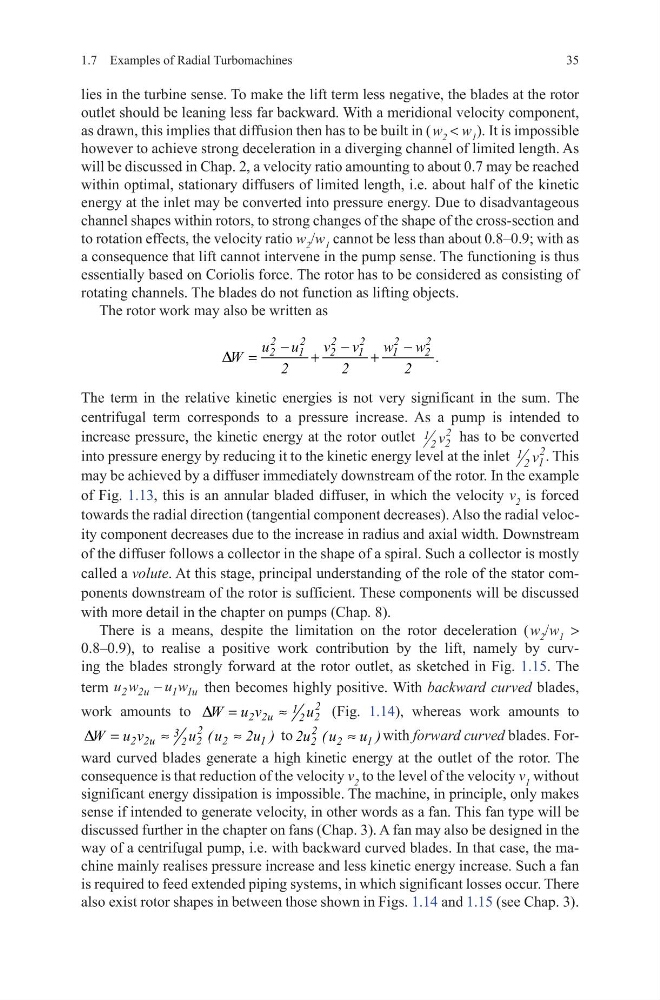
The rotor work may also be written as
The term in the relative kinetic energies is not very significant in the sum. The
centrifugal term corresponds to a pressure increase. As a pump is intended to
increase pressure, the kinetic energy at the rotor outlet 1 2 2
2
v has to be converted
into pressure energy by reducing it to the kinetic energy level at the inlet 1 2 1
2
v . This
may be achieved by a diffuser immediately downstream of the rotor. In the example
of Fig. 1.13, this is an annular bladed diffuser, in which the velocity v 2 is forced
towards the radial direction (tangential component decreases). Also the radial velocity component decreases due to the increase in radius and axial width. Downstream
of the diffuser follows a collector in the shape of a spiral. Such a collector is mostly
called a volute. At this stage, principal understanding of the role of the stator components downstream of the rotor is sufficient. These components will be discussed
with more detail in the chapter on pumps (Chap. 8).
There is a means, despite the limitation on the rotor deceleration ( w 2 /w 1 >
0.8–0.9), to realise a positive work contribution by the lift, namely by curving the blades strongly forward at the rotor outlet, as sketched in Fig. 1.15. The
term u w
u w
u
u
2 2
1 1
−
then becomes highly positive. With backward curved blades,
work amounts to
2
1
2 2u
2
2
W u v
u
D =
≈
(Fig. 1.14), whereas work amounts to
2
3
2 2u
2
2
1
2
W u v
u ( u
2u )
D =
≈
≈
to
2
2
2
1
2u ( u
u )
≈
with forward curved blades. Forward curved blades generate a high kinetic energy at the outlet of the rotor. The
consequence is that reduction of the velocity v 2 to the level of the velocity v 1 without
significant energy dissipation is impossible. The machine, in principle, only makes
sense if intended to generate velocity, in other words as a fan. This fan type will be
discussed further in the chapter on fans (Chap. 3). A fan may also be designed in the
way of a centrifugal pump, i.e. with backward curved blades. In that case, the machine mainly realises pressure increase and less kinetic energy increase. Such a fan
is required to feed extended piping systems, in which significant losses occur. There
also exist rotor shapes in between those shown in Figs. 1.14 and 1.15 (see Chap. 3).
2
2
2
2
2
2
2
1
2
1
1
2
u u
v v
w w
W
.
2
2
2
D
−
−
−
=
+
+
1.7 Examples of Radial Turbomachines
lies in the turbine sense. To make the lift term less negative, the blades at the rotor
outlet should be leaning less far backward. With a meridional velocity component,
as drawn, this implies that diffusion then has to be built in ( w 2 < w 1 ). It is impossible
however to achieve strong deceleration in a diverging channel of limited length. As
will be discussed in Chap. 2, a velocity ratio amounting to about 0.7 may be reached
within optimal, stationary diffusers of limited length, i.e. about half of the kinetic
energy at the inlet may be converted into pressure energy. Due to disadvantageous
channel shapes within rotors, to strong changes of the shape of the cross-section and
to rotation effects, the velocity ratio w 2 /w 1 cannot be less than about 0.8–0.9; with as
a consequence that lift cannot intervene in the pump sense. The functioning is thus
essentially based on Coriolis force. The rotor has to be considered as consisting of
rotating channels. The blades do not function as lifting objects.
The rotor work may also be written as
The term in the relative kinetic energies is not very significant in the sum. The
centrifugal term corresponds to a pressure increase. As a pump is intended to
increase pressure, the kinetic energy at the rotor outlet 1 2 2
2
v has to be converted
into pressure energy by reducing it to the kinetic energy level at the inlet 1 2 1
2
v . This
may be achieved by a diffuser immediately downstream of the rotor. In the example
of Fig. 1.13, this is an annular bladed diffuser, in which the velocity v 2 is forced
towards the radial direction (tangential component decreases). Also the radial velocity component decreases due to the increase in radius and axial width. Downstream
of the diffuser follows a collector in the shape of a spiral. Such a collector is mostly
called a volute. At this stage, principal understanding of the role of the stator components downstream of the rotor is sufficient. These components will be discussed
with more detail in the chapter on pumps (Chap. 8).
There is a means, despite the limitation on the rotor deceleration ( w 2 /w 1 >
0.8–0.9), to realise a positive work contribution by the lift, namely by curving the blades strongly forward at the rotor outlet, as sketched in Fig. 1.15. The
term u w
u w
u
u
2 2
1 1
−
then becomes highly positive. With backward curved blades,
work amounts to
2
1
2 2u
2
2
W u v
u
D =
≈
(Fig. 1.14), whereas work amounts to
2
3
2 2u
2
2
1
2
W u v
u ( u
2u )
D =
≈
≈
to
2
2
2
1
2u ( u
u )
≈
with forward curved blades. Forward curved blades generate a high kinetic energy at the outlet of the rotor. The
consequence is that reduction of the velocity v 2 to the level of the velocity v 1 without
significant energy dissipation is impossible. The machine, in principle, only makes
sense if intended to generate velocity, in other words as a fan. This fan type will be
discussed further in the chapter on fans (Chap. 3). A fan may also be designed in the
way of a centrifugal pump, i.e. with backward curved blades. In that case, the machine mainly realises pressure increase and less kinetic energy increase. Such a fan
is required to feed extended piping systems, in which significant losses occur. There
also exist rotor shapes in between those shown in Figs. 1.14 and 1.15 (see Chap. 3).
2
2
2
2
2
2
2
1
2
1
1
2
u u
v v
w w
W
.
2
2
2
D
−
−
−
=
+
+