

34
1 Working Principles
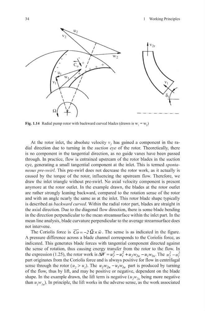
At the rotor inlet, the absolute velocity v 1 has gained a component in the radial direction due to turning in the suction eye of the rotor. Theoretically, there
is no component in the tangential direction, as no guide vanes have been passed
through. In practice, flow is entrained upstream of the rotor blades in the suction
eye, generating a small tangential component at the inlet. This is termed spontaneous pre-swirl. This pre-swirl does not decrease the rotor work, as it actually is
caused by the torque of the rotor, influencing the upstream flow. Therefore, we
draw the inlet triangle without pre-swirl. No axial velocity component is present
anymore at the rotor outlet. In the example drawn, the blades at the rotor outlet
are rather strongly leaning backward, compared to the rotation sense of the rotor
and with an angle nearly the same as at the inlet. This rotor blade shape typically
is described as backward curved. Within the radial rotor part, blades are straight in
the axial direction. Due to the diagonal flow direction, there is some blade bending
in the direction perpendicular to the mean streamsurface within the inlet part. In the
mean line analysis, blade curvature perpendicular to the average streamsurface does
not intervene.
The Coriolis force is Co
2
w
W
= −
×
. The sense is as indicated in the figure.
A pressure difference across a blade channel corresponds to the Coriolis force, as
indicated. This generates blade forces with tangential component directed against
the sense of rotation, thus causing energy transfer from the rotor to the flow. In
the expression (1.25), the rotor work is
2
2
2
1
2 2u
1 1u
W u u u w
u w
D =
− +
−
. The u u
2
2
1
2
−
part originates from the Coriolis force and is always positive for flow in centrifugal
sense through the rotor ( u 2 > u 1 ). The 2 2u
1 1u
u w
u w
−
part is produced by turning
of the flow, thus by lift, and may be positive or negative, dependent on the blade
shape. In the example drawn, the lift term is negative ( u 2 w 2u being more negative
than u 1 w 1u ). In principle, the lift works in the adverse sense, as the work associated
Fig. 1.14 Radial pump rotor with backward curved blades (drawn is w 1 = w 2 )
1 Working Principles
At the rotor inlet, the absolute velocity v 1 has gained a component in the radial direction due to turning in the suction eye of the rotor. Theoretically, there
is no component in the tangential direction, as no guide vanes have been passed
through. In practice, flow is entrained upstream of the rotor blades in the suction
eye, generating a small tangential component at the inlet. This is termed spontaneous pre-swirl. This pre-swirl does not decrease the rotor work, as it actually is
caused by the torque of the rotor, influencing the upstream flow. Therefore, we
draw the inlet triangle without pre-swirl. No axial velocity component is present
anymore at the rotor outlet. In the example drawn, the blades at the rotor outlet
are rather strongly leaning backward, compared to the rotation sense of the rotor
and with an angle nearly the same as at the inlet. This rotor blade shape typically
is described as backward curved. Within the radial rotor part, blades are straight in
the axial direction. Due to the diagonal flow direction, there is some blade bending
in the direction perpendicular to the mean streamsurface within the inlet part. In the
mean line analysis, blade curvature perpendicular to the average streamsurface does
not intervene.
The Coriolis force is Co
2
w
W
= −
×
. The sense is as indicated in the figure.
A pressure difference across a blade channel corresponds to the Coriolis force, as
indicated. This generates blade forces with tangential component directed against
the sense of rotation, thus causing energy transfer from the rotor to the flow. In
the expression (1.25), the rotor work is
2
2
2
1
2 2u
1 1u
W u u u w
u w
D =
− +
−
. The u u
2
2
1
2
−
part originates from the Coriolis force and is always positive for flow in centrifugal
sense through the rotor ( u 2 > u 1 ). The 2 2u
1 1u
u w
u w
−
part is produced by turning
of the flow, thus by lift, and may be positive or negative, dependent on the blade
shape. In the example drawn, the lift term is negative ( u 2 w 2u being more negative
than u 1 w 1u ). In principle, the lift works in the adverse sense, as the work associated
Fig. 1.14 Radial pump rotor with backward curved blades (drawn is w 1 = w 2 )