

33
1.7 Examples of Radial Turbomachines
The subscripts d and s refer to the discharge/delivery and suction sides of the pump.
The term manometric head denotes the mechanical energy rise by the pump, expressed as a height. Mostly, the term discharge side is used to denote the side by
which the pump delivers the fluid. Similarly, the term discharge pipe is used. We
will follow this practise.
1.7 Examples of Radial Turbomachines
In order to gain insight in the working principle of radial machines, we discuss
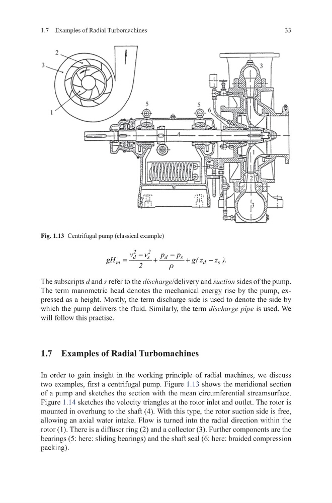
two examples, first a centrifugal pump. Figure 1.13 shows the meridional section
of a pump and sketches the section with the mean circumferential streamsurface.
Figure 1.14 sketches the velocity triangles at the rotor inlet and outlet. The rotor is
mounted in overhung to the shaft (4). With this type, the rotor suction side is free,
allowing an axial water intake. Flow is turned into the radial direction within the
rotor (1). There is a diffuser ring (2) and a collector (3). Further components are the
bearings (5: here: sliding bearings) and the shaft seal (6: here: braided compression
packing).
2
2
d
s
d
s
m
d
s
v v
p
p
gH
g( z
z ).
2
r
−
−
=
+
+
−
Fig. 1.13 Centrifugal pump (classical example)
1.7 Examples of Radial Turbomachines
The subscripts d and s refer to the discharge/delivery and suction sides of the pump.
The term manometric head denotes the mechanical energy rise by the pump, expressed as a height. Mostly, the term discharge side is used to denote the side by
which the pump delivers the fluid. Similarly, the term discharge pipe is used. We
will follow this practise.
1.7 Examples of Radial Turbomachines
In order to gain insight in the working principle of radial machines, we discuss
two examples, first a centrifugal pump. Figure 1.13 shows the meridional section
of a pump and sketches the section with the mean circumferential streamsurface.
Figure 1.14 sketches the velocity triangles at the rotor inlet and outlet. The rotor is
mounted in overhung to the shaft (4). With this type, the rotor suction side is free,
allowing an axial water intake. Flow is turned into the radial direction within the
rotor (1). There is a diffuser ring (2) and a collector (3). Further components are the
bearings (5: here: sliding bearings) and the shaft seal (6: here: braided compression
packing).
2
2
d
s
d
s
m
d
s
v v
p
p
gH
g( z
z ).
2
r
−
−
=
+
+
−
Fig. 1.13 Centrifugal pump (classical example)