

550
15 Axial and Radial Turbines for Gases
to the tangential direction. As the figure demonstrates, stator vanes normally direct
the flow somewhat more into the radial direction. From this also emerges that radial
turbines may be built without a stator vane ring. The rotor blades are purely radial
at the inlet. The gas is deflected into the axial direction in the meridional plane. At
the outlet, the gas has a significant tangential component in the relative frame. The
diffuser downstream of the rotor recovers pressure from the kinetic energy at outlet
and so decreases the pressure at the rotor outlet.
The principal functioning of a centripetal turbine for gas expansion does not
differ much from a hydraulic turbine of Francis type. Some parameters differ, however. The biggest difference is the rotor shape. The rotor is open and its outlet lies
in an orthogonal plane. There is an exducer part, analogous to the inducer part of a
radial compressor. An expansion turbine is normally designed for maximum rotor
work. This is commonly achieved by a high blade speed, typically around 400 m/s
at the rotor periphery. This requires an open rotor with purely radial blade form at
the rotor entry and an exducer part formed by radial filaments. As a consequence
of the expansion, the outlet area must be larger than the inlet area. A centripetal
gas expansion turbine features thus a rather high ratio of outlet diameter to inlet
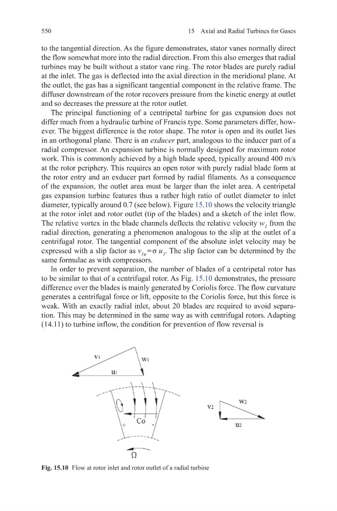
diameter, typically around 0.7 (see below). Figure 15.10 shows the velocity triangle
at the rotor inlet and rotor outlet (tip of the blades) and a sketch of the inlet flow.
The relative vortex in the blade channels deflects the relative velocity w 1 from the
radial direction, generating a phenomenon analogous to the slip at the outlet of a
centrifugal rotor. The tangential component of the absolute inlet velocity may be
expressed with a slip factor as v 1u = σ u 1 . The slip factor can be determined by the
same formulae as with compressors.
In order to prevent separation, the number of blades of a centripetal rotor has
to be similar to that of a centrifugal rotor. As Fig. 15.10 demonstrates, the pressure
difference over the blades is mainly generated by Coriolis force. The flow curvature
generates a centrifugal force or lift, opposite to the Coriolis force, but this force is
weak. With an exactly radial inlet, about 20 blades are required to avoid separation. This may be determined in the same way as with centrifugal rotors. Adapting
(14.11) to turbine inflow, the condition for prevention of flow reversal is
Fig. 15.10 Flow at rotor inlet and rotor outlet of a radial turbine
15 Axial and Radial Turbines for Gases
to the tangential direction. As the figure demonstrates, stator vanes normally direct
the flow somewhat more into the radial direction. From this also emerges that radial
turbines may be built without a stator vane ring. The rotor blades are purely radial
at the inlet. The gas is deflected into the axial direction in the meridional plane. At
the outlet, the gas has a significant tangential component in the relative frame. The
diffuser downstream of the rotor recovers pressure from the kinetic energy at outlet
and so decreases the pressure at the rotor outlet.
The principal functioning of a centripetal turbine for gas expansion does not
differ much from a hydraulic turbine of Francis type. Some parameters differ, however. The biggest difference is the rotor shape. The rotor is open and its outlet lies
in an orthogonal plane. There is an exducer part, analogous to the inducer part of a
radial compressor. An expansion turbine is normally designed for maximum rotor
work. This is commonly achieved by a high blade speed, typically around 400 m/s
at the rotor periphery. This requires an open rotor with purely radial blade form at
the rotor entry and an exducer part formed by radial filaments. As a consequence
of the expansion, the outlet area must be larger than the inlet area. A centripetal
gas expansion turbine features thus a rather high ratio of outlet diameter to inlet
diameter, typically around 0.7 (see below). Figure 15.10 shows the velocity triangle
at the rotor inlet and rotor outlet (tip of the blades) and a sketch of the inlet flow.
The relative vortex in the blade channels deflects the relative velocity w 1 from the
radial direction, generating a phenomenon analogous to the slip at the outlet of a
centrifugal rotor. The tangential component of the absolute inlet velocity may be
expressed with a slip factor as v 1u = σ u 1 . The slip factor can be determined by the
same formulae as with compressors.
In order to prevent separation, the number of blades of a centripetal rotor has
to be similar to that of a centrifugal rotor. As Fig. 15.10 demonstrates, the pressure
difference over the blades is mainly generated by Coriolis force. The flow curvature
generates a centrifugal force or lift, opposite to the Coriolis force, but this force is
weak. With an exactly radial inlet, about 20 blades are required to avoid separation. This may be determined in the same way as with centrifugal rotors. Adapting
(14.11) to turbine inflow, the condition for prevention of flow reversal is
Fig. 15.10 Flow at rotor inlet and rotor outlet of a radial turbine