

549
15.2 Radial Turbines
15.2 Radial Turbines
15.2.1 Shape and Functioning
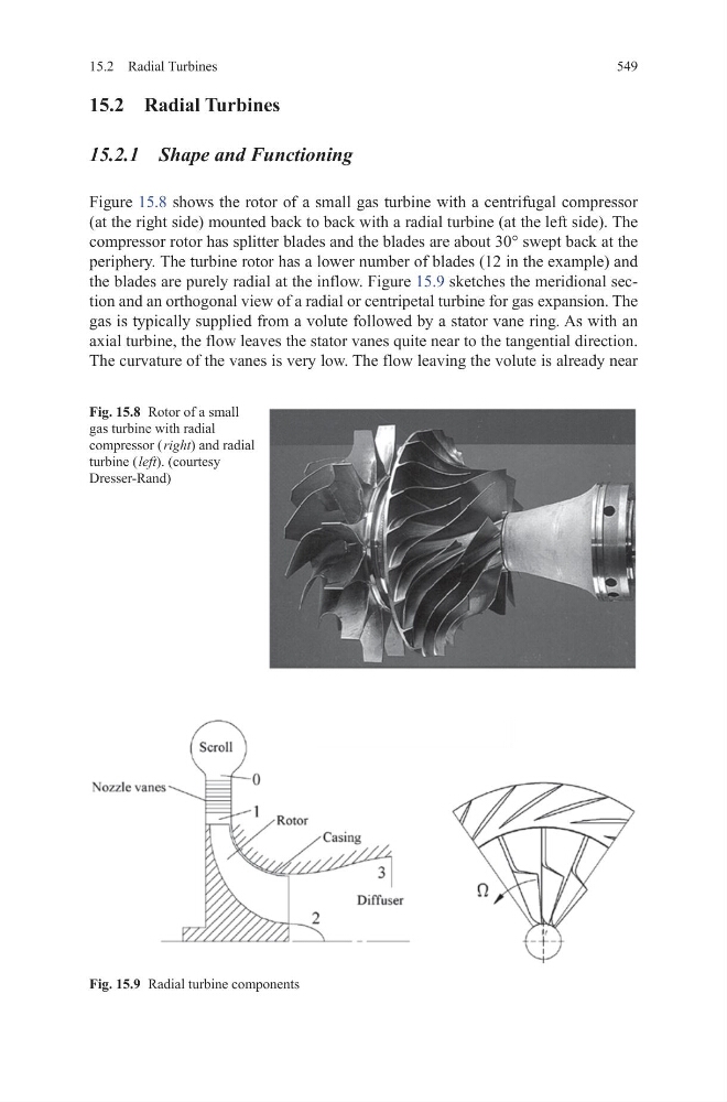
Figure 15.8 shows the rotor of a small gas turbine with a centrifugal compressor
(at the right side) mounted back to back with a radial turbine (at the left side). The
compressor rotor has splitter blades and the blades are about 30° swept back at the
periphery. The turbine rotor has a lower number of blades (12 in the example) and
the blades are purely radial at the inflow. Figure 15.9 sketches the meridional section and an orthogonal view of a radial or centripetal turbine for gas expansion. The
gas is typically supplied from a volute followed by a stator vane ring. As with an
axial turbine, the flow leaves the stator vanes quite near to the tangential direction.
The curvature of the vanes is very low. The flow leaving the volute is already near
Fig. 15.8 Rotor of a small
gas turbine with radial
compressor ( right) and radial
turbine ( left). (courtesy
Dresser-Rand)
Fig. 15.9 Radial turbine components
15.2 Radial Turbines
15.2 Radial Turbines
15.2.1 Shape and Functioning
Figure 15.8 shows the rotor of a small gas turbine with a centrifugal compressor
(at the right side) mounted back to back with a radial turbine (at the left side). The
compressor rotor has splitter blades and the blades are about 30° swept back at the
periphery. The turbine rotor has a lower number of blades (12 in the example) and
the blades are purely radial at the inflow. Figure 15.9 sketches the meridional section and an orthogonal view of a radial or centripetal turbine for gas expansion. The
gas is typically supplied from a volute followed by a stator vane ring. As with an
axial turbine, the flow leaves the stator vanes quite near to the tangential direction.
The curvature of the vanes is very low. The flow leaving the volute is already near
Fig. 15.8 Rotor of a small
gas turbine with radial
compressor ( right) and radial
turbine ( left). (courtesy
Dresser-Rand)
Fig. 15.9 Radial turbine components