

548
15 Axial and Radial Turbines for Gases
The term
2
1
1 1u
2
2
u v
u
−
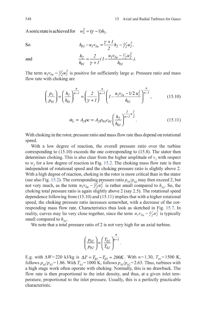
is positive for sufficiently large ψ. Pressure ratio and mass
flow rate with choking are
(15.10)
(15.11)
With choking in the rotor, pressure ratio and mass flow rate thus depend on rotational
speed.
With a low degree of reaction, the overall pressure ratio over the turbine
corresponding to (15.10) exceeds the one corresponding to (15.8). The stator then
determines choking. This is also clear from the higher amplitude of v 1 with respect
to w 2 for a low degree of reaction in Fig. 15.2. The choking mass flow rate is then
independent of rotational speed and the choking pressure ratio is slightly above 2.
With a high degree of reaction, choking in the rotor is more critical than in the stator
(see also Fig. 15.2). The corresponding pressure ratio p 01 /p 02 may then exceed 2, but
not very much, as the term
2
1
1 1u
2
2
u v
u
−
is rather small compared to h 01 . So, the
choking total pressure ratio is again slightly above 2 (say 2.5). The rotational speed
dependence following from (15.10) and (15.11) implies that with a higher rotational
speed, the choking pressure ratio increases somewhat, with a decrease of the corresponding mass flow rate. Characteristics thus look as sketched in Fig. 15.7. In
reality, curves may lie very close together, since the term u v
u
u
1 1
1 2 2
2
−
is typically
small compared to h 01 .
We note that a total pressure ratio of 2 is not very high for an axial turbine.
E.g. with ∆W = 220 kJ/kg is
01
02
T T
T
200K
∆ =
−
≈
. With n = 1.30, T 01 = 1500 K,
follows p 01 /p 02 = 1.86. With T 01 = 1000 K, follows p 01 /p 02 = 2.63. Thus, turbines with
a high stage work often operate with choking. Normally, this is no drawback. The
flow rate is then proportional to the inlet density, and thus, at a given inlet temperature, proportional to the inlet pressure. Usually, this is a perfectly practicable
characteristic.
2
2
2
A sonic state is achieved for
( 1) .
w
h
g
= −
So
and
2
1
01
1 1u
2
2
2
2
1
1 1u
2
2
2
01
01
1
h
u v
h
u ,
2
u v
u
h
2 ( 1
).
h
1
h
g
g
+
−
=
−
−
=
−
+
1/2
,
n
n
n
2 n 1
n 1
n 1
1 1u
2
2
2
01
01
01
u v
u
p
h
2
1
p
h
1
h
g
−
−
−
−
=
=
−
+
1 1
n 1 2
2
c
2
2 01 01
01
h
m
A c A
c
.
h
r
r
+
−
=
=
n
n 1
01
01
02
02
p
T
.
p
T
−
=
15 Axial and Radial Turbines for Gases
The term
2
1
1 1u
2
2
u v
u
−
is positive for sufficiently large ψ. Pressure ratio and mass
flow rate with choking are
(15.10)
(15.11)
With choking in the rotor, pressure ratio and mass flow rate thus depend on rotational
speed.
With a low degree of reaction, the overall pressure ratio over the turbine
corresponding to (15.10) exceeds the one corresponding to (15.8). The stator then
determines choking. This is also clear from the higher amplitude of v 1 with respect
to w 2 for a low degree of reaction in Fig. 15.2. The choking mass flow rate is then
independent of rotational speed and the choking pressure ratio is slightly above 2.
With a high degree of reaction, choking in the rotor is more critical than in the stator
(see also Fig. 15.2). The corresponding pressure ratio p 01 /p 02 may then exceed 2, but
not very much, as the term
2
1
1 1u
2
2
u v
u
−
is rather small compared to h 01 . So, the
choking total pressure ratio is again slightly above 2 (say 2.5). The rotational speed
dependence following from (15.10) and (15.11) implies that with a higher rotational
speed, the choking pressure ratio increases somewhat, with a decrease of the corresponding mass flow rate. Characteristics thus look as sketched in Fig. 15.7. In
reality, curves may lie very close together, since the term u v
u
u
1 1
1 2 2
2
−
is typically
small compared to h 01 .
We note that a total pressure ratio of 2 is not very high for an axial turbine.
E.g. with ∆W = 220 kJ/kg is
01
02
T T
T
200K
∆ =
−
≈
. With n = 1.30, T 01 = 1500 K,
follows p 01 /p 02 = 1.86. With T 01 = 1000 K, follows p 01 /p 02 = 2.63. Thus, turbines with
a high stage work often operate with choking. Normally, this is no drawback. The
flow rate is then proportional to the inlet density, and thus, at a given inlet temperature, proportional to the inlet pressure. Usually, this is a perfectly practicable
characteristic.
2
2
2
A sonic state is achieved for
( 1) .
w
h
g
= −
So
and
2
1
01
1 1u
2
2
2
2
1
1 1u
2
2
2
01
01
1
h
u v
h
u ,
2
u v
u
h
2 ( 1
).
h
1
h
g
g
+
−
=
−
−
=
−
+
1/2
,
n
n
n
2 n 1
n 1
n 1
1 1u
2
2
2
01
01
01
u v
u
p
h
2
1
p
h
1
h
g
−
−
−
−
=
=
−
+
1 1
n 1 2
2
c
2
2 01 01
01
h
m
A c A
c
.
h
r
r
+
−
=
=
n
n 1
01
01
02
02
p
T
.
p
T
−
=