

547
15.1 Axial Turbines
The corresponding pressure ratio and mass flow rate are
(15.8)
(15.9)
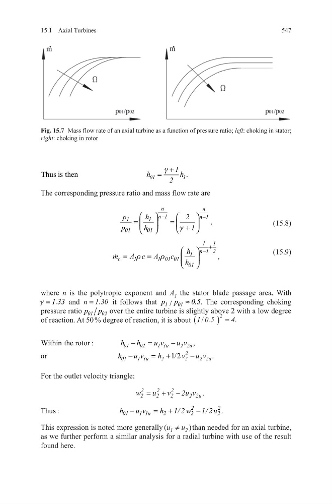
where n is the polytropic exponent and A 1 the stator blade passage area. With
1.33
g =
and n 1.30
=
it follows that
/
1
01
p p
0.5
≈ . The corresponding choking
pressure ratio 01 02
p p over the entire turbine is slightly above 2 with a low degree
of reaction. At 50 % degree of reaction, it is about 1 0.5
4
2
/
.
(
) =
For the outlet velocity triangle:
This expression is noted more generally (
)
u u
1
2
≠
than needed for an axial turbine,
as we further perform a similar analysis for a radial turbine with use of the result
found here.
Thus is then
.
01
1
1
h
h
2
g +
=
n
n
n 1
n 1
1
1
01
01
p
h
2
,
p
h
1
g
−
−
=
=
+
1 1
n 1 2
1
c
1
1 01 01
01
h
m
A c A
c
,
h
r
r
+
−
=
=
Within the rotor :
,
or
1/2
.
01
02
1 1u
2 2u
2
01
1 1u
2
2
2 2u
h
h
u v
u v
h
u v
h
v u v
−
=
−
−
= +
−
w
u v
u v u
2
2
2
2
2
2
2 2
2
= + −
.
Thus :
2
2
01
1 1u
2
2
2
h
u v
h 1/ 2 w 1/ 2 u .
−
= +
−
Fig. 15.7 Mass flow rate of an axial turbine as a function of pressure ratio; left: choking in stator;
right: choking in rotor
15.1 Axial Turbines
The corresponding pressure ratio and mass flow rate are
(15.8)
(15.9)
where n is the polytropic exponent and A 1 the stator blade passage area. With
1.33
g =
and n 1.30
=
it follows that
/
1
01
p p
0.5
≈ . The corresponding choking
pressure ratio 01 02
p p over the entire turbine is slightly above 2 with a low degree
of reaction. At 50 % degree of reaction, it is about 1 0.5
4
2
/
.
(
) =
For the outlet velocity triangle:
This expression is noted more generally (
)
u u
1
2
≠
than needed for an axial turbine,
as we further perform a similar analysis for a radial turbine with use of the result
found here.
Thus is then
.
01
1
1
h
h
2
g +
=
n
n
n 1
n 1
1
1
01
01
p
h
2
,
p
h
1
g
−
−
=
=
+
1 1
n 1 2
1
c
1
1 01 01
01
h
m
A c A
c
,
h
r
r
+
−
=
=
Within the rotor :
,
or
1/2
.
01
02
1 1u
2 2u
2
01
1 1u
2
2
2 2u
h
h
u v
u v
h
u v
h
v u v
−
=
−
−
= +
−
w
u v
u v u
2
2
2
2
2
2
2 2
2
= + −
.
Thus :
2
2
01
1 1u
2
2
2
h
u v
h 1/ 2 w 1/ 2 u .
−
= +
−
Fig. 15.7 Mass flow rate of an axial turbine as a function of pressure ratio; left: choking in stator;
right: choking in rotor