

546
15 Axial and Radial Turbines for Gases
turbines (Chap. 6, Sect. 6.9.2). Observe the combined sweep and lean of some stator vanes at the casing in the LP turbine part in Fig. 12.9 (Trent 800). Sweep is also
visible in Fig. 12.14.
15.1.5 Vane and Blade Clocking
Clocking is setting the relative position of two subsequent stators (or rotors) with an
equal number of blades. Maximum efficiency is obtained when wake segments of
the upstream row impinge the leading edge of the downstream row. The efficiency
is lowest when the wake segments follow a path midway the downstream blades as
then wake mixing is the strongest and so is the mixing loss. The principle is also
used with axial compressors. A subtle difference is that with turbines it is mostly
advantageous to shift the impacting wake somewhat to the suction side. This helps
in promoting transition in the suction side boundary layer. The possible adiabatic
efficiency improvement with clocking is in the order of 0.5 percentage points, similarly with turbines and compressors.
15.1.6 Operating Characteristic of Axial Turbines
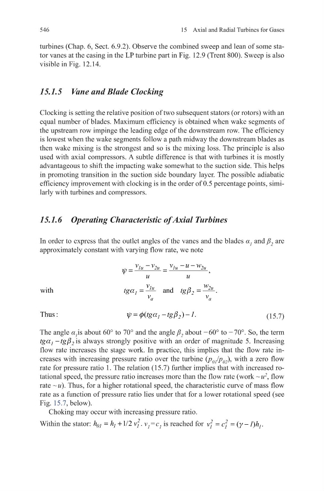
In order to express that the outlet angles of the vanes and the blades α 1 and β 2 are
approximately constant with varying flow rate, we note
(15.7)
The angle α 1 is about 60° to 70° and the angle β 2 about − 60° to − 70°. So, the term
1
2
tg
tg
a
b
−
is always strongly positive with an order of magnitude 5. Increasing
flow rate increases the stage work. In practice, this implies that the flow rate increases with increasing pressure ratio over the turbine ( p 01 /p 02 ), with a zero flow
rate for pressure ratio 1. The relation (15.7) further implies that with increased rotational speed, the pressure ratio increases more than the flow rate (work ~ u
2
, flow
rate ~ u). Thus, for a higher rotational speed, the characteristic curve of mass flow
rate as a function of pressure ratio lies under that for a lower rotational speed (see
Fig. 15.7, below).
Choking may occur with increasing pressure ratio.
Within the stator:
1/2 .
2
01
1
1
h
h
v
= +
v 1 = c 1 is reached for
(
) .
2
2
1
1
1
v
c
1 h
g
= = −
,
with
and
.
1u
2u
1u
2u
1u
2u
1
2
a
a
v
v
v
u w
u
u
v
w
tg
tg
v
v
y
a
b
−
− −
=
=
=
=
Thus :
(
) .
1
2
tg
tg
1
y f a
b
=
−
−
15 Axial and Radial Turbines for Gases
turbines (Chap. 6, Sect. 6.9.2). Observe the combined sweep and lean of some stator vanes at the casing in the LP turbine part in Fig. 12.9 (Trent 800). Sweep is also
visible in Fig. 12.14.
15.1.5 Vane and Blade Clocking
Clocking is setting the relative position of two subsequent stators (or rotors) with an
equal number of blades. Maximum efficiency is obtained when wake segments of
the upstream row impinge the leading edge of the downstream row. The efficiency
is lowest when the wake segments follow a path midway the downstream blades as
then wake mixing is the strongest and so is the mixing loss. The principle is also
used with axial compressors. A subtle difference is that with turbines it is mostly
advantageous to shift the impacting wake somewhat to the suction side. This helps
in promoting transition in the suction side boundary layer. The possible adiabatic
efficiency improvement with clocking is in the order of 0.5 percentage points, similarly with turbines and compressors.
15.1.6 Operating Characteristic of Axial Turbines
In order to express that the outlet angles of the vanes and the blades α 1 and β 2 are
approximately constant with varying flow rate, we note
(15.7)
The angle α 1 is about 60° to 70° and the angle β 2 about − 60° to − 70°. So, the term
1
2
tg
tg
a
b
−
is always strongly positive with an order of magnitude 5. Increasing
flow rate increases the stage work. In practice, this implies that the flow rate increases with increasing pressure ratio over the turbine ( p 01 /p 02 ), with a zero flow
rate for pressure ratio 1. The relation (15.7) further implies that with increased rotational speed, the pressure ratio increases more than the flow rate (work ~ u
2
, flow
rate ~ u). Thus, for a higher rotational speed, the characteristic curve of mass flow
rate as a function of pressure ratio lies under that for a lower rotational speed (see
Fig. 15.7, below).
Choking may occur with increasing pressure ratio.
Within the stator:
1/2 .
2
01
1
1
h
h
v
= +
v 1 = c 1 is reached for
(
) .
2
2
1
1
1
v
c
1 h
g
= = −
,
with
and
.
1u
2u
1u
2u
1u
2u
1
2
a
a
v
v
v
u w
u
u
v
w
tg
tg
v
v
y
a
b
−
− −
=
=
=
=
Thus :
(
) .
1
2
tg
tg
1
y f a
b
=
−
−