

545
15.1 Axial Turbines
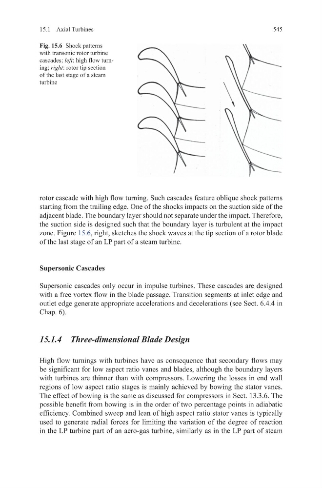
rotor cascade with high flow turning. Such cascades feature oblique shock patterns
starting from the trailing edge. One of the shocks impacts on the suction side of the
adjacent blade. The boundary layer should not separate under the impact. Therefore,
the suction side is designed such that the boundary layer is turbulent at the impact
zone. Figure 15.6, right, sketches the shock waves at the tip section of a rotor blade
of the last stage of an LP part of a steam turbine.
Supersonic Cascades
Supersonic cascades only occur in impulse turbines. These cascades are designed
with a free vortex flow in the blade passage. Transition segments at inlet edge and
outlet edge generate appropriate accelerations and decelerations (see Sect. 6.4.4 in
Chap. 6).
15.1.4 Three-dimensional Blade Design
High flow turnings with turbines have as consequence that secondary flows may
be significant for low aspect ratio vanes and blades, although the boundary layers
with turbines are thinner than with compressors. Lowering the losses in end wall
regions of low aspect ratio stages is mainly achieved by bowing the stator vanes.
The effect of bowing is the same as discussed for compressors in Sect. 13.3.6. The
possible benefit from bowing is in the order of two percentage points in adiabatic
efficiency. Combined sweep and lean of high aspect ratio stator vanes is typically
used to generate radial forces for limiting the variation of the degree of reaction
in the LP turbine part of an aero-gas turbine, similarly as in the LP part of steam
Fig. 15.6 Shock patterns
with transonic rotor turbine
cascades; left: high flow turning; right: rotor tip section
of the last stage of a steam
turbine
15.1 Axial Turbines
rotor cascade with high flow turning. Such cascades feature oblique shock patterns
starting from the trailing edge. One of the shocks impacts on the suction side of the
adjacent blade. The boundary layer should not separate under the impact. Therefore,
the suction side is designed such that the boundary layer is turbulent at the impact
zone. Figure 15.6, right, sketches the shock waves at the tip section of a rotor blade
of the last stage of an LP part of a steam turbine.
Supersonic Cascades
Supersonic cascades only occur in impulse turbines. These cascades are designed
with a free vortex flow in the blade passage. Transition segments at inlet edge and
outlet edge generate appropriate accelerations and decelerations (see Sect. 6.4.4 in
Chap. 6).
15.1.4 Three-dimensional Blade Design
High flow turnings with turbines have as consequence that secondary flows may
be significant for low aspect ratio vanes and blades, although the boundary layers
with turbines are thinner than with compressors. Lowering the losses in end wall
regions of low aspect ratio stages is mainly achieved by bowing the stator vanes.
The effect of bowing is the same as discussed for compressors in Sect. 13.3.6. The
possible benefit from bowing is in the order of two percentage points in adiabatic
efficiency. Combined sweep and lean of high aspect ratio stator vanes is typically
used to generate radial forces for limiting the variation of the degree of reaction
in the LP turbine part of an aero-gas turbine, similarly as in the LP part of steam
Fig. 15.6 Shock patterns
with transonic rotor turbine
cascades; left: high flow turning; right: rotor tip section
of the last stage of a steam
turbine