

551
15.2 Radial Turbines
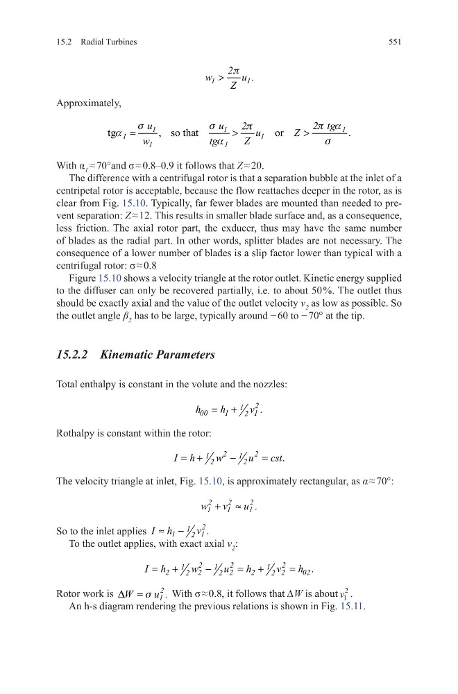
Approximately,
With α 1 ≈ 70°and σ ≈ 0.8–0.9 it follows that Z ≈ 20.
The difference with a centrifugal rotor is that a separation bubble at the inlet of a
centripetal rotor is acceptable, because the flow reattaches deeper in the rotor, as is
clear from Fig. 15.10. Typically, far fewer blades are mounted than needed to prevent separation: Z ≈ 12. This results in smaller blade surface and, as a consequence,
less friction. The axial rotor part, the exducer, thus may have the same number
of blades as the radial part. In other words, splitter blades are not necessary. The
consequence of a lower number of blades is a slip factor lower than typical with a
centrifugal rotor: σ ≈ 0.8
Figure 15.10 shows a velocity triangle at the rotor outlet. Kinetic energy supplied
to the diffuser can only be recovered partially, i.e. to about 50 %. The outlet thus
should be exactly axial and the value of the outlet velocity v 2 as low as possible. So
the outlet angle β 2 has to be large, typically around − 60 to − 70° at the tip.
15.2.2 Kinematic Parameters
Total enthalpy is constant in the volute and the nozzles:
Rothalpy is constant within the rotor:
The velocity triangle at inlet, Fig. 15.10, is approximately rectangular, as α ≈ 70°:
So to the inlet applies
2
1
1
1
2
I h
v .
≈ −
To the outlet applies, with exact axial v 2 :
Rotor work is
2
1
W
u .
D
s
=
With σ ≈ 0.8, it follows that ∆W is about v 1
2
.
An h-s diagram rendering the previous relations is shown in Fig. 15.11.
1
1
2
w
u .
Z
p
>
tg
, so that
or
.
1
1
1
1
1
1
1
u
u
2 tg
2 u
Z
w
tg
Z
s
s
p a
p
a
a
s
=
>
>
2
1
00
1
1
2
h
h
v .
= +
2
2
1
1
2
2
I h
w
u
cst.
= +
−
=
2
2
2
1
1
1
w v
u .
+ ≈
2
2
2
1
1
1
2
2
2
2
2
02
2
2
2
I h
w
u
h
v
h .
= +
−
= +
=
15.2 Radial Turbines
Approximately,
With α 1 ≈ 70°and σ ≈ 0.8–0.9 it follows that Z ≈ 20.
The difference with a centrifugal rotor is that a separation bubble at the inlet of a
centripetal rotor is acceptable, because the flow reattaches deeper in the rotor, as is
clear from Fig. 15.10. Typically, far fewer blades are mounted than needed to prevent separation: Z ≈ 12. This results in smaller blade surface and, as a consequence,
less friction. The axial rotor part, the exducer, thus may have the same number
of blades as the radial part. In other words, splitter blades are not necessary. The
consequence of a lower number of blades is a slip factor lower than typical with a
centrifugal rotor: σ ≈ 0.8
Figure 15.10 shows a velocity triangle at the rotor outlet. Kinetic energy supplied
to the diffuser can only be recovered partially, i.e. to about 50 %. The outlet thus
should be exactly axial and the value of the outlet velocity v 2 as low as possible. So
the outlet angle β 2 has to be large, typically around − 60 to − 70° at the tip.
15.2.2 Kinematic Parameters
Total enthalpy is constant in the volute and the nozzles:
Rothalpy is constant within the rotor:
The velocity triangle at inlet, Fig. 15.10, is approximately rectangular, as α ≈ 70°:
So to the inlet applies
2
1
1
1
2
I h
v .
≈ −
To the outlet applies, with exact axial v 2 :
Rotor work is
2
1
W
u .
D
s
=
With σ ≈ 0.8, it follows that ∆W is about v 1
2
.
An h-s diagram rendering the previous relations is shown in Fig. 15.11.
1
1
2
w
u .
Z
p
>
tg
, so that
or
.
1
1
1
1
1
1
1
u
u
2 tg
2 u
Z
w
tg
Z
s
s
p a
p
a
a
s
=
>
>
2
1
00
1
1
2
h
h
v .
= +
2
2
1
1
2
2
I h
w
u
cst.
= +
−
=
2
2
2
1
1
1
w v
u .
+ ≈
2
2
2
1
1
1
2
2
2
2
2
02
2
2
2
I h
w
u
h
v
h .
= +
−
= +
=