

527
14.5 Diffusers
14.5.3 Vaneless Diffusers
Vaneless diffusers with parallel walls are applied in compressors with moderate
rotor work. The diffuser inlet velocity is then subsonic. They are also applied as
an entry part of a vaned diffuser in compressors with large rotor work. The outlet
velocity of the impeller may then be supersonic. The vaneless space is then meant
to mix the jet and wake flows and to decrease the Mach number level of the flow.
In a vaneless diffuser, streamlines are long due to the small flow angle with
respect to the tangential direction. Long streamlines result in large friction loss and
thick boundary layers. The streamline length increases when the flow rate decreases. As streamlines run rather tangentially and the pressure gradient is in the radial
direction, boundary layers do not have much momentum in the pressure gradient
direction. There is thus a strong tendency towards flow reversal in the radial direction within the boundary layers. At low flow rate, radial backflow occurs within the
boundary layers. The backflow forms in cells rotating in the rotor running sense,
analogous to rotating stall in a vane system. Choking can only occur if the radial
velocity attains the speed of sound. This never happens in practice. No shock waves
can occur and there is no incidence loss. All these features together cause a vaneless diffuser to be well suited when the velocity reduction downstream of the rotor
is moderate. For strong deceleration, the necessary radial dimensions become big,
which means big losses and strong risk for flow instability.
14.5.4 Vaned Diffusers
Mounting vanes aims at forcing the streamlines into a more radial direction than attained by a vaneless diffuser. With a large rotor work, the tangential velocity component at the impeller outlet is much bigger than the radial component (see Fig. 14.3).
Therefore, reduction of the tangential velocity component becomes increasingly
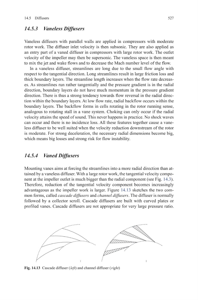
advantageous as the impeller work is larger. Figure 14.13 sketches the two common forms, called cascade diffusers and channel diffusers. The diffuser is normally
followed by a collector scroll. Cascade diffusers are built with curved plates or
profiled vanes. Cascade diffusers are not appropriate for very large pressure ratio.
Fig. 14.13 Cascade diffuser ( left) and channel diffuser ( right)
14.5 Diffusers
14.5.3 Vaneless Diffusers
Vaneless diffusers with parallel walls are applied in compressors with moderate
rotor work. The diffuser inlet velocity is then subsonic. They are also applied as
an entry part of a vaned diffuser in compressors with large rotor work. The outlet
velocity of the impeller may then be supersonic. The vaneless space is then meant
to mix the jet and wake flows and to decrease the Mach number level of the flow.
In a vaneless diffuser, streamlines are long due to the small flow angle with
respect to the tangential direction. Long streamlines result in large friction loss and
thick boundary layers. The streamline length increases when the flow rate decreases. As streamlines run rather tangentially and the pressure gradient is in the radial
direction, boundary layers do not have much momentum in the pressure gradient
direction. There is thus a strong tendency towards flow reversal in the radial direction within the boundary layers. At low flow rate, radial backflow occurs within the
boundary layers. The backflow forms in cells rotating in the rotor running sense,
analogous to rotating stall in a vane system. Choking can only occur if the radial
velocity attains the speed of sound. This never happens in practice. No shock waves
can occur and there is no incidence loss. All these features together cause a vaneless diffuser to be well suited when the velocity reduction downstream of the rotor
is moderate. For strong deceleration, the necessary radial dimensions become big,
which means big losses and strong risk for flow instability.
14.5.4 Vaned Diffusers
Mounting vanes aims at forcing the streamlines into a more radial direction than attained by a vaneless diffuser. With a large rotor work, the tangential velocity component at the impeller outlet is much bigger than the radial component (see Fig. 14.3).
Therefore, reduction of the tangential velocity component becomes increasingly
advantageous as the impeller work is larger. Figure 14.13 sketches the two common forms, called cascade diffusers and channel diffusers. The diffuser is normally
followed by a collector scroll. Cascade diffusers are built with curved plates or
profiled vanes. Cascade diffusers are not appropriate for very large pressure ratio.
Fig. 14.13 Cascade diffuser ( left) and channel diffuser ( right)