

474
13 Axial Compressors
rotor and the stator. The associated centrifugal force causes a higher pressure at the
casing and a lower one at the hub. A stage is normally designed with the same work
on all radii. Because of the greater pressure rise within the rotor at the casing and
the lower pressure rise at the hub, the degree of reaction increases from the hub to
the casing. For example, with R = 0.7 on the average radius, R ≈ 0.8 at the casing and
R ≈ 0.5 at the hub may be expected at ratios for outer and inner radii r r
o
m
/
.
= 1 2
and r r
i
m
/ = 0.75 (a detailed analysis follows in Sect. 13.3). With ψ ~ 1/u
2
, the velocity triangles are as sketched in Fig. 13.9. We note that the rotor blades have a
strong twist and that the flow turnings in rotor and stator are the largest at the hub.
13.1.10 Optimisation of a Stage
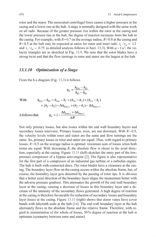
From the h-s diagram (Fig. 13.3) it follows
Not only primary losses, but also losses within the end wall boundary layers and
secondary losses intervene. Primary losses, even, are not dominant. With R = 0.5,
the velocity levels within rotor and stator are the same and flow turnings are the
same. So, primary losses in rotor and stator are equal. Thus, with regard to primary
losses, R = 0.5 on the average radius is optimal: minimum sum of losses when both
terms are equal. With increasing R, the absolute flow is closer to the axial direction, especially at the casing. Figure 13.11 (left) sketches the entry part of the lowpressure compressor of a bypass aero-engine [2]. The figure is also representative
for the first part of a compressor of an industrial gas turbine or a turbofan engine.
The hub is built with connected discs. The rotor blades have a clearance at the casing. The boundary layer flow on the casing occurs within the absolute frame, but, of
course, the boundary layer gets distorted by the passing of rotor tips. It is obvious
that a better axial direction of the boundary layer aligns the momentum better with
the adverse pressure gradient. This attenuates the growth of the end wall boundary
layer at the casing, causing a decrease of losses in this boundary layer and a decrease of the intensity of the secondary flows generated. A high degree of reaction
at the casing is therefore favourable for reduction of secondary losses and boundary
layer losses at the casing. Figure 13.11 (right) shows that stator vanes have cover
bands with labyrinth seals at the hub [16]. The end wall boundary layer at the hub
alternately flows in the absolute frame and the relative frame. Therefore, with regard to minimisation of the whole of losses, 50 % degree of reaction at the hub is
optimum (symmetry between rotor and stator).
03
01
03
01
.
s
tt
h
h
h
h
−
=
−
h
(
) (
)
With
(
)
(
)
,
−
≈
− ≈
−
+
−
=
−
−
+
−
−
03s
01
3ss
1
3s
2
2s
1
3
2
loss,s
2
1
loss,r
h
h
h
h
h
h
h
h
h h
h
h h
h
D
D
,
,
it follows that
1
.
∆
+ ∆
≈ −
∆
loss s
loss r
tt
h
h
W
h
13 Axial Compressors
rotor and the stator. The associated centrifugal force causes a higher pressure at the
casing and a lower one at the hub. A stage is normally designed with the same work
on all radii. Because of the greater pressure rise within the rotor at the casing and
the lower pressure rise at the hub, the degree of reaction increases from the hub to
the casing. For example, with R = 0.7 on the average radius, R ≈ 0.8 at the casing and
R ≈ 0.5 at the hub may be expected at ratios for outer and inner radii r r
o
m
/
.
= 1 2
and r r
i
m
/ = 0.75 (a detailed analysis follows in Sect. 13.3). With ψ ~ 1/u
2
, the velocity triangles are as sketched in Fig. 13.9. We note that the rotor blades have a
strong twist and that the flow turnings in rotor and stator are the largest at the hub.
13.1.10 Optimisation of a Stage
From the h-s diagram (Fig. 13.3) it follows
Not only primary losses, but also losses within the end wall boundary layers and
secondary losses intervene. Primary losses, even, are not dominant. With R = 0.5,
the velocity levels within rotor and stator are the same and flow turnings are the
same. So, primary losses in rotor and stator are equal. Thus, with regard to primary
losses, R = 0.5 on the average radius is optimal: minimum sum of losses when both
terms are equal. With increasing R, the absolute flow is closer to the axial direction, especially at the casing. Figure 13.11 (left) sketches the entry part of the lowpressure compressor of a bypass aero-engine [2]. The figure is also representative
for the first part of a compressor of an industrial gas turbine or a turbofan engine.
The hub is built with connected discs. The rotor blades have a clearance at the casing. The boundary layer flow on the casing occurs within the absolute frame, but, of
course, the boundary layer gets distorted by the passing of rotor tips. It is obvious
that a better axial direction of the boundary layer aligns the momentum better with
the adverse pressure gradient. This attenuates the growth of the end wall boundary
layer at the casing, causing a decrease of losses in this boundary layer and a decrease of the intensity of the secondary flows generated. A high degree of reaction
at the casing is therefore favourable for reduction of secondary losses and boundary
layer losses at the casing. Figure 13.11 (right) shows that stator vanes have cover
bands with labyrinth seals at the hub [16]. The end wall boundary layer at the hub
alternately flows in the absolute frame and the relative frame. Therefore, with regard to minimisation of the whole of losses, 50 % degree of reaction at the hub is
optimum (symmetry between rotor and stator).
03
01
03
01
.
s
tt
h
h
h
h
−
=
−
h
(
) (
)
With
(
)
(
)
,
−
≈
− ≈
−
+
−
=
−
−
+
−
−
03s
01
3ss
1
3s
2
2s
1
3
2
loss,s
2
1
loss,r
h
h
h
h
h
h
h
h
h h
h
h h
h
D
D
,
,
it follows that
1
.
∆
+ ∆
≈ −
∆
loss s
loss r
tt
h
h
W
h