

471
13.1 Mean Line Analysis
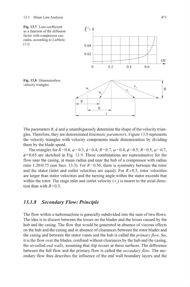
The parameters R, ϕ and ψ unambiguously determine the shape of the velocity triangles. Therefore, they are denominated kinematic parameters. Figure 13.8 represents
the velocity triangles with velocity components made dimensionless by dividing
them by the blade speed.
The triangles for R = 0.8, ψ = 0.3, ϕ = 0.4; R = 0.7, ψ = 0.4, ϕ = 0.5; R = 0.5, ψ = 0.7,
ϕ = 0.65 are sketched in Fig. 13.9. These combinations are representative for the
flow near the casing, at mean radius and near the hub of a compressor with radius
ratio 1.20/0.75 (see Sect. 13.3). For R = 0.50, there is symmetry between the rotor
and the stator (inlet and outlet velocities are equal). For R > 0.5, rotor velocities
are larger than stator velocities and the turning angle within the stator exceeds that
within the rotor. The stage inlet and outlet velocity ( v 1 ) is nearer to the axial direction than with R = 0.5.
13.1.8 Secondary Flow: Principle
The flow within a turbomachine is generally subdivided into the sum of two flows.
The idea is to discern between the losses on the blades and the losses caused by the
hub and the casing. The flow that would be generated in absence of viscous effects
on the hub and the casing and in absence of clearances between the rotor blades and
the casing and between the stator vanes and the hub is called the primary flow. So,
it is the flow over the blades, confined without clearances by the hub and the casing,
the so-called end walls, assuming that slip occurs at these surfaces. The difference
between the full flow and the primary flow is called the secondary flow. The secondary flow thus describes the influence of the end wall boundary layers and the
Fig. 13.7 Loss coefficient
as a function of the diffusion
factor with compressor cascades, according to Lieblein
[11]
Fig. 13.8 Dimensionless
velocity triangles
13.1 Mean Line Analysis
The parameters R, ϕ and ψ unambiguously determine the shape of the velocity triangles. Therefore, they are denominated kinematic parameters. Figure 13.8 represents
the velocity triangles with velocity components made dimensionless by dividing
them by the blade speed.
The triangles for R = 0.8, ψ = 0.3, ϕ = 0.4; R = 0.7, ψ = 0.4, ϕ = 0.5; R = 0.5, ψ = 0.7,
ϕ = 0.65 are sketched in Fig. 13.9. These combinations are representative for the
flow near the casing, at mean radius and near the hub of a compressor with radius
ratio 1.20/0.75 (see Sect. 13.3). For R = 0.50, there is symmetry between the rotor
and the stator (inlet and outlet velocities are equal). For R > 0.5, rotor velocities
are larger than stator velocities and the turning angle within the stator exceeds that
within the rotor. The stage inlet and outlet velocity ( v 1 ) is nearer to the axial direction than with R = 0.5.
13.1.8 Secondary Flow: Principle
The flow within a turbomachine is generally subdivided into the sum of two flows.
The idea is to discern between the losses on the blades and the losses caused by the
hub and the casing. The flow that would be generated in absence of viscous effects
on the hub and the casing and in absence of clearances between the rotor blades and
the casing and between the stator vanes and the hub is called the primary flow. So,
it is the flow over the blades, confined without clearances by the hub and the casing,
the so-called end walls, assuming that slip occurs at these surfaces. The difference
between the full flow and the primary flow is called the secondary flow. The secondary flow thus describes the influence of the end wall boundary layers and the
Fig. 13.7 Loss coefficient
as a function of the diffusion
factor with compressor cascades, according to Lieblein
[11]
Fig. 13.8 Dimensionless
velocity triangles