

468
13 Axial Compressors
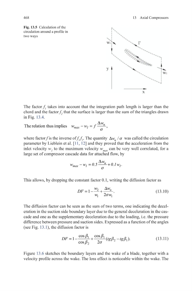
The factor f 1 takes into account that the integration path length is larger than the
chord and the factor f 2 that the surface is larger than the sum of the triangles drawn
in Fig. 13.4.
where factor f is the inverse of f 1 f 2 . The quantity
/
u
w
∆
s was called the circulation
parameter by Lieblein et al. [11, 12] and they proved that the acceleration from the
inlet velocity w 1 to the maximum velocity w max can be very well correlated, for a
large set of compressor cascade data for attached flow, by
This allows, by dropping the constant factor 0.1, writing the diffusion factor as
(13.10)
The diffusion factor can be seen as the sum of two terms, one indicating the deceleration in the suction side boundary layer due to the general deceleration in the cascade and one as the supplementary deceleration due to the loading, i.e. the pressure
difference between pressure and suction sides. Expressed as a function of the angles
(see Fig. 13.1), the diffusion factor is
(13.11)
Figure 13.6 sketches the boundary layers and the wake of a blade, together with a
velocity profile across the wake. The loss effect is noticeable within the wake. The
The relation thus imp
,
lies
− =
u
max
1
w
w
w
f
D
s
− =
+
u
max
1
1
w
w
w 0.5
0.1w .
D
s
2
1
1
1
.
2
u
w
w
DF
w
w
∆
= −
+ s
1
1
2
1
2
cos
cos
1
(
).
cos
2
DF
tg
tg
= −
+
−
b
b
b
b
b
s
Fig. 13.5 Calculation of the
circulation around a profile in
two ways
13 Axial Compressors
The factor f 1 takes into account that the integration path length is larger than the
chord and the factor f 2 that the surface is larger than the sum of the triangles drawn
in Fig. 13.4.
where factor f is the inverse of f 1 f 2 . The quantity
/
u
w
∆
s was called the circulation
parameter by Lieblein et al. [11, 12] and they proved that the acceleration from the
inlet velocity w 1 to the maximum velocity w max can be very well correlated, for a
large set of compressor cascade data for attached flow, by
This allows, by dropping the constant factor 0.1, writing the diffusion factor as
(13.10)
The diffusion factor can be seen as the sum of two terms, one indicating the deceleration in the suction side boundary layer due to the general deceleration in the cascade and one as the supplementary deceleration due to the loading, i.e. the pressure
difference between pressure and suction sides. Expressed as a function of the angles
(see Fig. 13.1), the diffusion factor is
(13.11)
Figure 13.6 sketches the boundary layers and the wake of a blade, together with a
velocity profile across the wake. The loss effect is noticeable within the wake. The
The relation thus imp
,
lies
− =
u
max
1
w
w
w
f
D
s
− =
+
u
max
1
1
w
w
w 0.5
0.1w .
D
s
2
1
1
1
.
2
u
w
w
DF
w
w
∆
= −
+ s
1
1
2
1
2
cos
cos
1
(
).
cos
2
DF
tg
tg
= −
+
−
b
b
b
b
b
s
Fig. 13.5 Calculation of the
circulation around a profile in
two ways