

467
13.1 Mean Line Analysis
There are variants of the diffusion factor definition. In Chap. 3 we applied the
local diffusion factor D loc . An expression better related to external parameters is the
diffusion factor DF (name without any further specification).
(13.9)
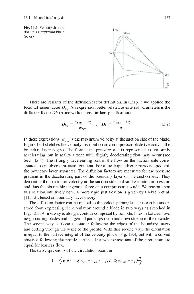
In these expressions, w max is the maximum velocity at the suction side of the blade.
Figure 13.4 sketches the velocity distribution on a compressor blade (velocity at the
boundary layer edges). The flow at the pressure side is represented as uniformly
accelerating, but in reality a zone with slightly decelerating flow may occur (see
Sect. 13.4). The strongly decelerating part in the flow on the suction side corresponds to an adverse pressure gradient. For a too large adverse pressure gradient,
the boundary layer separates. The diffusion factors are measures for the pressure
gradient in the decelerating part of the boundary layer on the suction side. They
determine the maximum velocity at the suction side and so the minimum pressure
and thus the obtainable tangential force on a compressor cascade. We reason upon
this relation intuitively here. A more rigid justification is given by Lieblein et al.
[11, 12], based on boundary layer theory.
The diffusion factor can be related to the velocity triangles. This can be understood from expressing the circulation around a blade in two ways as sketched in
Fig. 13.5. A first way is along a contour composed by periodic lines in between two
neighbouring blades and tangential parts upstream and downstream of the cascade.
The second way is along a contour following the edges of the boundary layers
and cutting through the wake of the profile. With this second way, the circulation
is equal to the surface integral of the velocity plot of Fig. 13.4, but with a curved
abscissa following the profile surface. The two expressions of the circulation are
equal for lossless flow.
The two expressions of the circulation result in
max
2
max
2
max
1
,
.
loc
w
w
w
w
D
DF
w
w
−
−
=
=
=
=
−
=
−
∫
2u
1u
1 2
max
1
c
w d
s( w
w ) f f 2( w
w ) .
2
G
Fig. 13.4 Velocity distribution on a compressor blade
(rotor)
13.1 Mean Line Analysis
There are variants of the diffusion factor definition. In Chap. 3 we applied the
local diffusion factor D loc . An expression better related to external parameters is the
diffusion factor DF (name without any further specification).
(13.9)
In these expressions, w max is the maximum velocity at the suction side of the blade.
Figure 13.4 sketches the velocity distribution on a compressor blade (velocity at the
boundary layer edges). The flow at the pressure side is represented as uniformly
accelerating, but in reality a zone with slightly decelerating flow may occur (see
Sect. 13.4). The strongly decelerating part in the flow on the suction side corresponds to an adverse pressure gradient. For a too large adverse pressure gradient,
the boundary layer separates. The diffusion factors are measures for the pressure
gradient in the decelerating part of the boundary layer on the suction side. They
determine the maximum velocity at the suction side and so the minimum pressure
and thus the obtainable tangential force on a compressor cascade. We reason upon
this relation intuitively here. A more rigid justification is given by Lieblein et al.
[11, 12], based on boundary layer theory.
The diffusion factor can be related to the velocity triangles. This can be understood from expressing the circulation around a blade in two ways as sketched in
Fig. 13.5. A first way is along a contour composed by periodic lines in between two
neighbouring blades and tangential parts upstream and downstream of the cascade.
The second way is along a contour following the edges of the boundary layers
and cutting through the wake of the profile. With this second way, the circulation
is equal to the surface integral of the velocity plot of Fig. 13.4, but with a curved
abscissa following the profile surface. The two expressions of the circulation are
equal for lossless flow.
The two expressions of the circulation result in
max
2
max
2
max
1
,
.
loc
w
w
w
w
D
DF
w
w
−
−
=
=
=
=
−
=
−
∫
2u
1u
1 2
max
1
c
w d
s( w
w ) f f 2( w
w ) .
2
G
Fig. 13.4 Velocity distribution on a compressor blade
(rotor)