

461
13.1 Mean Line Analysis
13.1.2 Fundamental Equations
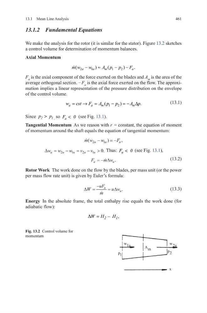
We make the analysis for the rotor (it is similar for the stator). Figure 13.2 sketches
a control volume for determination of momentum balances.
Axial Momentum
F a is the axial component of the force exerted on the blades and A m is the area of the
average orthogonal section. − F a is the axial force exerted on the flow. The approximation implies a linear representation of the pressure distribution on the envelope
of the control volume.
(13.1)
Since 2
1
p
p
>
,
so a
F
0
<
(see Fig. 13.1).
Tangential Momentum As we reason with r = constant, the equation of moment
of momentum around the shaft equals the equation of tangential momentum:
∆w w
w
v
v
u
u
u
u
u
=
−
=
−
>
2
1
2
1
0. Thus: u
F
0
<
(see Fig. 13.1),
(13.2)
Rotor Work The work done on the flow by the blades, per mass unit (or the power
per mass flow rate unit) is given by Euler’s formula:
(13.3)
Energy In the absolute frame, the total enthalpy rise equals the work done (for
adiabatic flow):
2
1
1
2
(
)
(
)
.
a
a
m
a
m w
w
A p p
F
−
≈
−
−
1
2
(
)
.
a
a
m
m
w
cst
F
A p p
A p
=
→
=
−
= − ∆
m w
w
F
u
u
u
(
)
,
2
1
−
=−
F
m w
u
u
= − ∆ .
∆
∆
W
uF
m
u w
u
u
=
−
=
.
,
=
−
2
1
W H
H
D
[
D
Z
S
D
Z
P
$
S
Fig. 13.2 Control volume for
momentum
13.1 Mean Line Analysis
13.1.2 Fundamental Equations
We make the analysis for the rotor (it is similar for the stator). Figure 13.2 sketches
a control volume for determination of momentum balances.
Axial Momentum
F a is the axial component of the force exerted on the blades and A m is the area of the
average orthogonal section. − F a is the axial force exerted on the flow. The approximation implies a linear representation of the pressure distribution on the envelope
of the control volume.
(13.1)
Since 2
1
p
p
>
,
so a
F
0
<
(see Fig. 13.1).
Tangential Momentum As we reason with r = constant, the equation of moment
of momentum around the shaft equals the equation of tangential momentum:
∆w w
w
v
v
u
u
u
u
u
=
−
=
−
>
2
1
2
1
0. Thus: u
F
0
<
(see Fig. 13.1),
(13.2)
Rotor Work The work done on the flow by the blades, per mass unit (or the power
per mass flow rate unit) is given by Euler’s formula:
(13.3)
Energy In the absolute frame, the total enthalpy rise equals the work done (for
adiabatic flow):
2
1
1
2
(
)
(
)
.
a
a
m
a
m w
w
A p p
F
−
≈
−
−
1
2
(
)
.
a
a
m
m
w
cst
F
A p p
A p
=
→
=
−
= − ∆
m w
w
F
u
u
u
(
)
,
2
1
−
=−
F
m w
u
u
= − ∆ .
∆
∆
W
uF
m
u w
u
u
=
−
=
.
,
=
−
2
1
W H
H
D
[
D
Z
S
D
Z
P
$
S
Fig. 13.2 Control volume for
momentum