

460
13 Axial Compressors
13.1.1 Velocity Triangles
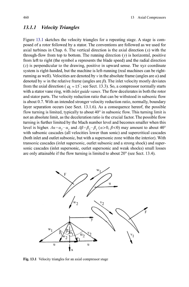
Figure 13.1 sketches the velocity triangles for a repeating stage. A stage is composed of a rotor followed by a stator. The conventions are followed as we used for
axial turbines in Chap. 6. The vertical direction is the axial direction ( x) with the
through-flow from top to bottom. The running direction ( y) is horizontal, positive
from left to right (the symbol u represents the blade speed) and the radial direction
( z) is perpendicular to the drawing, positive in upward sense. The xyz coordinate
system is right-handed, but the machine is left-running (real machines can be rightrunning as well). Velocities are denoted by v in the absolute frame (angles are α) and
denoted by w in the relative frame (angles are β). The inlet velocity mostly deviates
from the axial direction ( 1 15
°
≈
α
; see Sect. 13.3). So, a compressor normally starts
with a stator vane ring, with inlet guide vanes. The flow decelerates in both the rotor
and stator parts. The velocity reduction ratio that can be withstood in subsonic flow
is about 0.7. With an intended stronger velocity reduction ratio, normally, boundary
layer separation occurs (see Sect. 13.1.6). As a consequence hereof, the possible
flow turning is limited, typically to about 40° in subsonic flow. This turning limit is
not an absolute limit, as the deceleration ratio is the crucial factor. The possible flow
turning is further limited by the Mach number level and becomes smaller when this
level is higher. Δα = α 2 − α 1 and Δβ = β 2 − β 1 ( α > 0, β < 0) may amount to about 40°
with subsonic cascades (all velocities lower than sonic) and supercritical cascades
(both inlet and outlet subsonic, but with a supersonic zone within the interior). With
transonic cascades (inlet supersonic, outlet subsonic and a strong shock) and supersonic cascades (inlet supersonic, outlet supersonic and weak shocks) small losses
are only attainable if the flow turning is limited to about 20° (see Sect. 13.4).
)
X
X
[
X
)
\
Z
Y
Y
Z
Z
Y
Y
α
α
β
β
Z
Fig. 13.1 Velocity triangles for an axial compressor stage
13 Axial Compressors
13.1.1 Velocity Triangles
Figure 13.1 sketches the velocity triangles for a repeating stage. A stage is composed of a rotor followed by a stator. The conventions are followed as we used for
axial turbines in Chap. 6. The vertical direction is the axial direction ( x) with the
through-flow from top to bottom. The running direction ( y) is horizontal, positive
from left to right (the symbol u represents the blade speed) and the radial direction
( z) is perpendicular to the drawing, positive in upward sense. The xyz coordinate
system is right-handed, but the machine is left-running (real machines can be rightrunning as well). Velocities are denoted by v in the absolute frame (angles are α) and
denoted by w in the relative frame (angles are β). The inlet velocity mostly deviates
from the axial direction ( 1 15
°
≈
α
; see Sect. 13.3). So, a compressor normally starts
with a stator vane ring, with inlet guide vanes. The flow decelerates in both the rotor
and stator parts. The velocity reduction ratio that can be withstood in subsonic flow
is about 0.7. With an intended stronger velocity reduction ratio, normally, boundary
layer separation occurs (see Sect. 13.1.6). As a consequence hereof, the possible
flow turning is limited, typically to about 40° in subsonic flow. This turning limit is
not an absolute limit, as the deceleration ratio is the crucial factor. The possible flow
turning is further limited by the Mach number level and becomes smaller when this
level is higher. Δα = α 2 − α 1 and Δβ = β 2 − β 1 ( α > 0, β < 0) may amount to about 40°
with subsonic cascades (all velocities lower than sonic) and supercritical cascades
(both inlet and outlet subsonic, but with a supersonic zone within the interior). With
transonic cascades (inlet supersonic, outlet subsonic and a strong shock) and supersonic cascades (inlet supersonic, outlet supersonic and weak shocks) small losses
are only attainable if the flow turning is limited to about 20° (see Sect. 13.4).
)
X
X
[
X
)
\
Z
Y
Y
Z
Z
Y
Y
α
α
β
β
Z
Fig. 13.1 Velocity triangles for an axial compressor stage