

462
13 Axial Compressors
with
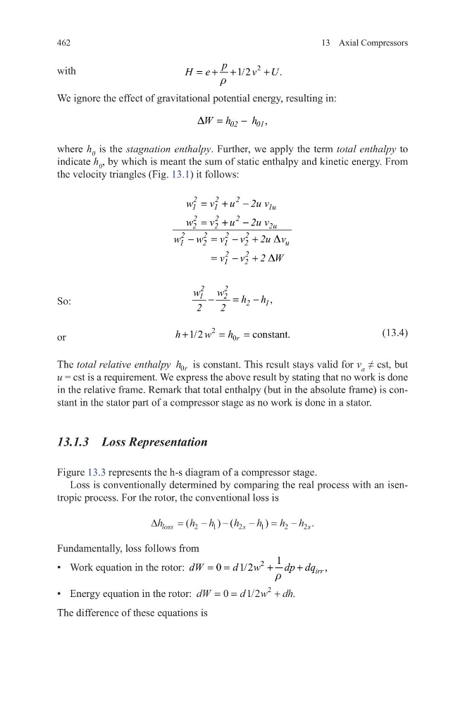
We ignore the effect of gravitational potential energy, resulting in:
where h 0 is the stagnation enthalpy. Further, we apply the term total enthalpy to
indicate h 0 , by which is meant the sum of static enthalpy and kinetic energy. From
the velocity triangles (Fig. 13.1) it follows:
So:
or
(13.4)
The total relative enthalpy h r
0 is constant. This result stays valid for v a ≠ cst, but
u = cst is a requirement. We express the above result by stating that no work is done
in the relative frame. Remark that total enthalpy (but in the absolute frame) is constant in the stator part of a compressor stage as no work is done in a stator.
13.1.3 Loss Representation
Figure 13.3 represents the h-s diagram of a compressor stage.
Loss is conventionally determined by comparing the real process with an isentropic process. For the rotor, the conventional loss is
Fundamentally, loss follows from
• Work equation in the rotor:
2
1
0
1/2
,
irr
dW
d w
dp dq
r
= =
+
+
• Energy equation in the rotor: dW
d w dh
= =
+
0
1 2
2
/
.
The difference of these equations is
2
1/2
.
p
H e
v U
r
= + +
+
,
=
−
02
01
W h
h
D
2
2
2
1
1
1u
2
2
2
2
2
2u
2
2
2
2
1
2
1
2
u
2
2
1
2
w
v u 2u v
w
v u 2u v
w w
v v 2u v
v v 2 W
= + −
= + −
−
= − +
= − +
D
D
,
−
= −
2
2
1
2
2
1
w
w
h h
2
2
2
0
constant
1/2
.
r
h
w
h
+
=
=
∆h
h h
h
h
h h
loss
s
s
=
− −
−
= −
(
) (
)
.
2
1
2
1
2
2
13 Axial Compressors
with
We ignore the effect of gravitational potential energy, resulting in:
where h 0 is the stagnation enthalpy. Further, we apply the term total enthalpy to
indicate h 0 , by which is meant the sum of static enthalpy and kinetic energy. From
the velocity triangles (Fig. 13.1) it follows:
So:
or
(13.4)
The total relative enthalpy h r
0 is constant. This result stays valid for v a ≠ cst, but
u = cst is a requirement. We express the above result by stating that no work is done
in the relative frame. Remark that total enthalpy (but in the absolute frame) is constant in the stator part of a compressor stage as no work is done in a stator.
13.1.3 Loss Representation
Figure 13.3 represents the h-s diagram of a compressor stage.
Loss is conventionally determined by comparing the real process with an isentropic process. For the rotor, the conventional loss is
Fundamentally, loss follows from
• Work equation in the rotor:
2
1
0
1/2
,
irr
dW
d w
dp dq
r
= =
+
+
• Energy equation in the rotor: dW
d w dh
= =
+
0
1 2
2
/
.
The difference of these equations is
2
1/2
.
p
H e
v U
r
= + +
+
,
=
−
02
01
W h
h
D
2
2
2
1
1
1u
2
2
2
2
2
2u
2
2
2
2
1
2
1
2
u
2
2
1
2
w
v u 2u v
w
v u 2u v
w w
v v 2u v
v v 2 W
= + −
= + −
−
= − +
= − +
D
D
,
−
= −
2
2
1
2
2
1
w
w
h h
2
2
2
0
constant
1/2
.
r
h
w
h
+
=
=
∆h
h h
h
h
h h
loss
s
s
=
− −
−
= −
(
) (
)
.
2
1
2
1
2
2