

445
12.5 Performance of Double-Flow Engines
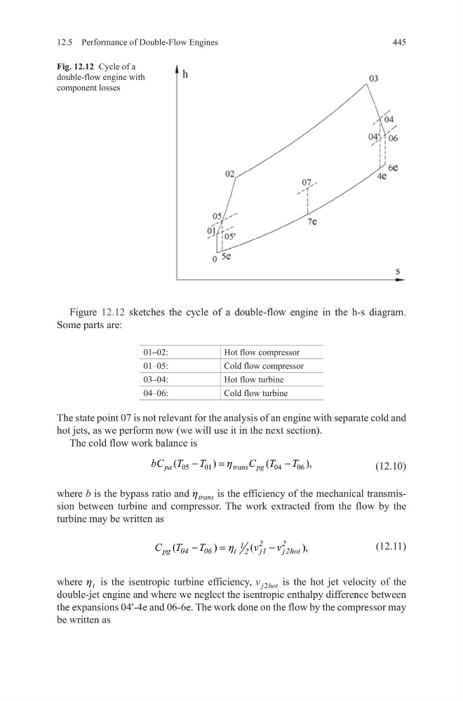
Figure 12.12 sketches the cycle of a double-flow engine in the h-s diagram.
Some parts are:
01–02:
Hot flow compressor
01–05:
Cold flow compressor
03–04:
Hot flow turbine
04–06:
Cold flow turbine
The state point 07 is not relevant for the analysis of an engine with separate cold and
hot jets, as we perform now (we will use it in the next section).
The cold flow work balance is
(12.10)
where b is the bypass ratio and trans
h
is the efficiency of the mechanical transmission between turbine and compressor. The work extracted from the flow by the
turbine may be written as
(12.11)
where t
h is the isentropic turbine efficiency, v j hot
2
is the hot jet velocity of the
double-jet engine and where we neglect the isentropic enthalpy difference between
the expansions 04ʹ-4e and 06-6e. The work done on the flow by the compressor may
be written as
05
01
04
06
(
)
(
),
pa
trans pg
bC T
T
C T
T
h
−
=
−
(
)
(
),
−
=
−
2
2
1
pg 04
06
t
j1
j2hot
2
C T
T
v
v
h
Fig. 12.12 Cycle of a
double-flow engine with
component losses
12.5 Performance of Double-Flow Engines
Figure 12.12 sketches the cycle of a double-flow engine in the h-s diagram.
Some parts are:
01–02:
Hot flow compressor
01–05:
Cold flow compressor
03–04:
Hot flow turbine
04–06:
Cold flow turbine
The state point 07 is not relevant for the analysis of an engine with separate cold and
hot jets, as we perform now (we will use it in the next section).
The cold flow work balance is
(12.10)
where b is the bypass ratio and trans
h
is the efficiency of the mechanical transmission between turbine and compressor. The work extracted from the flow by the
turbine may be written as
(12.11)
where t
h is the isentropic turbine efficiency, v j hot
2
is the hot jet velocity of the
double-jet engine and where we neglect the isentropic enthalpy difference between
the expansions 04ʹ-4e and 06-6e. The work done on the flow by the compressor may
be written as
05
01
04
06
(
)
(
),
pa
trans pg
bC T
T
C T
T
h
−
=
−
(
)
(
),
−
=
−
2
2
1
pg 04
06
t
j1
j2hot
2
C T
T
v
v
h
Fig. 12.12 Cycle of a
double-flow engine with
component losses