

428
12 Thrust Gas Turbines
ning at a much lower rotational speed than the core part, i.e. the part on the external
hollow shaft. A turbo-shaft is similar, but, in principle, no thrust is generated by a
nozzle. So, basically, a turbo-shaft does not differ from a power gas turbine, except
that a gearbox is integrated. A typical turbo-shaft application is helicopter rotor
drive (but some thrust may be generated with an outlet nozzle). Such gas turbines
are also applied to drive heavy vehicles as off-road trucks.
12.2.3 Bypass Turbojet
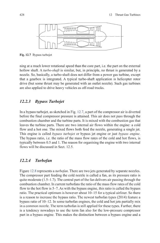
In a bypass turbojet, as sketched in Fig. 12.7, a part of the compressor air is diverted
before the final compressor pressure is attained. This air does not pass through the
combustion chamber and the turbine parts. It is mixed with the combustion gas that
leaves the turbine parts. There are two internal air flows within the engine: a cold
flow and a hot one. The mixed flows both feed the nozzle, generating a single jet.
This engine is called bypass turbojet or bypass jet engine or just bypass engine.
The bypass ratio, i.e. the ratio of the mass flow rates of the cold and hot flows, is
typically between 0.5 and 1. The reason for organising the engine with two internal
flows will be discussed in Sect. 12.5.
12.2.4 Turbofan
Figure 12.8 represents a turbofan. There are two jets generated by separate nozzles.
The compressor part feeding the cold nozzle is called a fan, as its pressure ratio is
quite moderate (1.5–1.7). The central part of the fan delivers air passing through the
combustion chamber. In current turbofans the ratio of the mass flow rates of the cold
flow to the hot flow is 5–7. As with the bypass engine, this ratio is called the bypass
ratio. The practical optimum is however about 10–15 for a typical airliner. So there
is a reason to increase the bypass ratio. The newest turbofan types (2014) feature a
bypass ratio of 10–12. In some turbofan engines, the cold and hot jets partially mix
in a common nozzle. The term turbofan is still applied for these types. Further, there
is a tendency nowadays to use the term fan also for the low-pressure compressor
part in a bypass engine. This makes the distinction between a bypass engine and a
Fig. 12.7 Bypass turbojet
12 Thrust Gas Turbines
ning at a much lower rotational speed than the core part, i.e. the part on the external
hollow shaft. A turbo-shaft is similar, but, in principle, no thrust is generated by a
nozzle. So, basically, a turbo-shaft does not differ from a power gas turbine, except
that a gearbox is integrated. A typical turbo-shaft application is helicopter rotor
drive (but some thrust may be generated with an outlet nozzle). Such gas turbines
are also applied to drive heavy vehicles as off-road trucks.
12.2.3 Bypass Turbojet
In a bypass turbojet, as sketched in Fig. 12.7, a part of the compressor air is diverted
before the final compressor pressure is attained. This air does not pass through the
combustion chamber and the turbine parts. It is mixed with the combustion gas that
leaves the turbine parts. There are two internal air flows within the engine: a cold
flow and a hot one. The mixed flows both feed the nozzle, generating a single jet.
This engine is called bypass turbojet or bypass jet engine or just bypass engine.
The bypass ratio, i.e. the ratio of the mass flow rates of the cold and hot flows, is
typically between 0.5 and 1. The reason for organising the engine with two internal
flows will be discussed in Sect. 12.5.
12.2.4 Turbofan
Figure 12.8 represents a turbofan. There are two jets generated by separate nozzles.
The compressor part feeding the cold nozzle is called a fan, as its pressure ratio is
quite moderate (1.5–1.7). The central part of the fan delivers air passing through the
combustion chamber. In current turbofans the ratio of the mass flow rates of the cold
flow to the hot flow is 5–7. As with the bypass engine, this ratio is called the bypass
ratio. The practical optimum is however about 10–15 for a typical airliner. So there
is a reason to increase the bypass ratio. The newest turbofan types (2014) feature a
bypass ratio of 10–12. In some turbofan engines, the cold and hot jets partially mix
in a common nozzle. The term turbofan is still applied for these types. Further, there
is a tendency nowadays to use the term fan also for the low-pressure compressor
part in a bypass engine. This makes the distinction between a bypass engine and a
Fig. 12.7 Bypass turbojet