

427
12.2 Overview of Aircraft Gas Turbine Engines
12.2 Overview of Aircraft Gas Turbine Engines
12.2.1 Turbojet
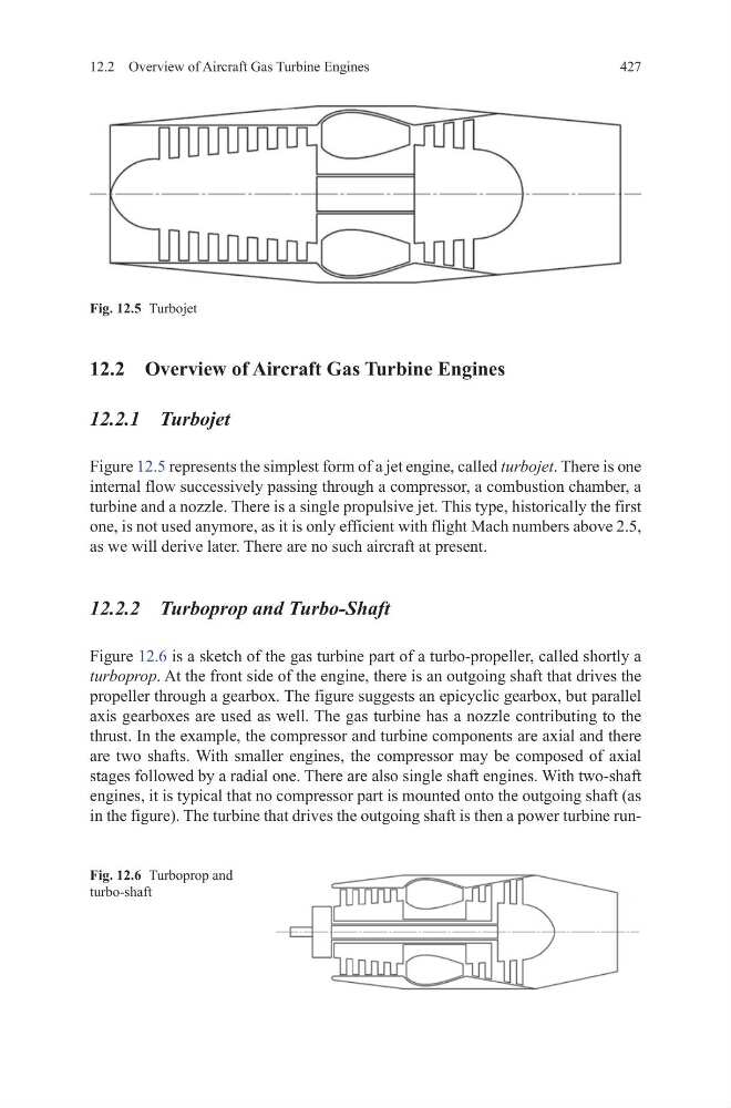
Figure 12.5 represents the simplest form of a jet engine, called turbojet. There is one
internal flow successively passing through a compressor, a combustion chamber, a
turbine and a nozzle. There is a single propulsive jet. This type, historically the first
one, is not used anymore, as it is only efficient with flight Mach numbers above 2.5,
as we will derive later. There are no such aircraft at present.
12.2.2 Turboprop and Turbo-Shaft
Figure 12.6 is a sketch of the gas turbine part of a turbo-propeller, called shortly a
turboprop. At the front side of the engine, there is an outgoing shaft that drives the
propeller through a gearbox. The figure suggests an epicyclic gearbox, but parallel
axis gearboxes are used as well. The gas turbine has a nozzle contributing to the
thrust. In the example, the compressor and turbine components are axial and there
are two shafts. With smaller engines, the compressor may be composed of axial
stages followed by a radial one. There are also single shaft engines. With two-shaft
engines, it is typical that no compressor part is mounted onto the outgoing shaft (as
in the figure). The turbine that drives the outgoing shaft is then a power turbine runFig. 12.5 Turbojet
Fig. 12.6 Turboprop and
turbo-shaft
12.2 Overview of Aircraft Gas Turbine Engines
12.2 Overview of Aircraft Gas Turbine Engines
12.2.1 Turbojet
Figure 12.5 represents the simplest form of a jet engine, called turbojet. There is one
internal flow successively passing through a compressor, a combustion chamber, a
turbine and a nozzle. There is a single propulsive jet. This type, historically the first
one, is not used anymore, as it is only efficient with flight Mach numbers above 2.5,
as we will derive later. There are no such aircraft at present.
12.2.2 Turboprop and Turbo-Shaft
Figure 12.6 is a sketch of the gas turbine part of a turbo-propeller, called shortly a
turboprop. At the front side of the engine, there is an outgoing shaft that drives the
propeller through a gearbox. The figure suggests an epicyclic gearbox, but parallel
axis gearboxes are used as well. The gas turbine has a nozzle contributing to the
thrust. In the example, the compressor and turbine components are axial and there
are two shafts. With smaller engines, the compressor may be composed of axial
stages followed by a radial one. There are also single shaft engines. With two-shaft
engines, it is typical that no compressor part is mounted onto the outgoing shaft (as
in the figure). The turbine that drives the outgoing shaft is then a power turbine runFig. 12.5 Turbojet
Fig. 12.6 Turboprop and
turbo-shaft