

423
12.1 Thrust Generation
12.1.2 Reactor or Jet Engine
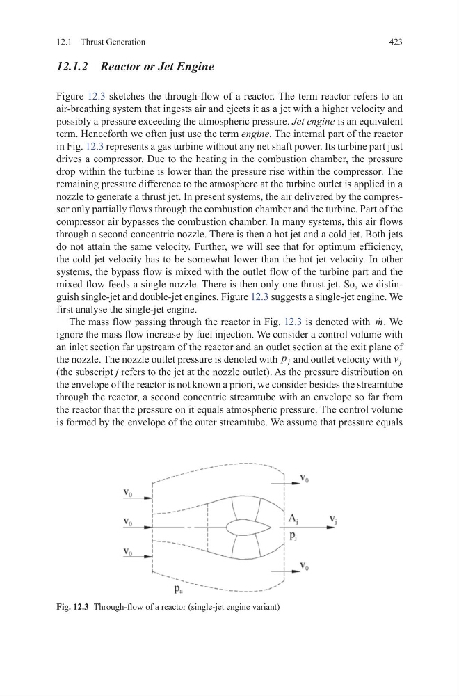
Figure 12.3 sketches the through-flow of a reactor. The term reactor refers to an
air-breathing system that ingests air and ejects it as a jet with a higher velocity and
possibly a pressure exceeding the atmospheric pressure. Jet engine is an equivalent
term. Henceforth we often just use the term engine. The internal part of the reactor
in Fig. 12.3 represents a gas turbine without any net shaft power. Its turbine part just
drives a compressor. Due to the heating in the combustion chamber, the pressure
drop within the turbine is lower than the pressure rise within the compressor. The
remaining pressure difference to the atmosphere at the turbine outlet is applied in a
nozzle to generate a thrust jet. In present systems, the air delivered by the compressor only partially flows through the combustion chamber and the turbine. Part of the
compressor air bypasses the combustion chamber. In many systems, this air flows
through a second concentric nozzle. There is then a hot jet and a cold jet. Both jets
do not attain the same velocity. Further, we will see that for optimum efficiency,
the cold jet velocity has to be somewhat lower than the hot jet velocity. In other
systems, the bypass flow is mixed with the outlet flow of the turbine part and the
mixed flow feeds a single nozzle. There is then only one thrust jet. So, we distinguish single-jet and double-jet engines. Figure 12.3 suggests a single-jet engine. We
first analyse the single-jet engine.
The mass flow passing through the reactor in Fig. 12.3 is denoted with
m. We
ignore the mass flow increase by fuel injection. We consider a control volume with
an inlet section far upstream of the reactor and an outlet section at the exit plane of
the nozzle. The nozzle outlet pressure is denoted with p j and outlet velocity with v j
(the subscript j refers to the jet at the nozzle outlet). As the pressure distribution on
the envelope of the reactor is not known a priori, we consider besides the streamtube
through the reactor, a second concentric streamtube with an envelope so far from
the reactor that the pressure on it equals atmospheric pressure. The control volume
is formed by the envelope of the outer streamtube. We assume that pressure equals
Fig. 12.3 Through-flow of a reactor (single-jet engine variant)
12.1 Thrust Generation
12.1.2 Reactor or Jet Engine
Figure 12.3 sketches the through-flow of a reactor. The term reactor refers to an
air-breathing system that ingests air and ejects it as a jet with a higher velocity and
possibly a pressure exceeding the atmospheric pressure. Jet engine is an equivalent
term. Henceforth we often just use the term engine. The internal part of the reactor
in Fig. 12.3 represents a gas turbine without any net shaft power. Its turbine part just
drives a compressor. Due to the heating in the combustion chamber, the pressure
drop within the turbine is lower than the pressure rise within the compressor. The
remaining pressure difference to the atmosphere at the turbine outlet is applied in a
nozzle to generate a thrust jet. In present systems, the air delivered by the compressor only partially flows through the combustion chamber and the turbine. Part of the
compressor air bypasses the combustion chamber. In many systems, this air flows
through a second concentric nozzle. There is then a hot jet and a cold jet. Both jets
do not attain the same velocity. Further, we will see that for optimum efficiency,
the cold jet velocity has to be somewhat lower than the hot jet velocity. In other
systems, the bypass flow is mixed with the outlet flow of the turbine part and the
mixed flow feeds a single nozzle. There is then only one thrust jet. So, we distinguish single-jet and double-jet engines. Figure 12.3 suggests a single-jet engine. We
first analyse the single-jet engine.
The mass flow passing through the reactor in Fig. 12.3 is denoted with
m. We
ignore the mass flow increase by fuel injection. We consider a control volume with
an inlet section far upstream of the reactor and an outlet section at the exit plane of
the nozzle. The nozzle outlet pressure is denoted with p j and outlet velocity with v j
(the subscript j refers to the jet at the nozzle outlet). As the pressure distribution on
the envelope of the reactor is not known a priori, we consider besides the streamtube
through the reactor, a second concentric streamtube with an envelope so far from
the reactor that the pressure on it equals atmospheric pressure. The control volume
is formed by the envelope of the outer streamtube. We assume that pressure equals
Fig. 12.3 Through-flow of a reactor (single-jet engine variant)