

421
12.1 Thrust Generation
The dD w
. 1 part is the dissipated part of the power exchanged (see Chap. 2). This
part reaches the flow as heat. The −dD v
. 1 part causes exchange of mechanical energy. This part is negative with the velocity triangle drawn in Fig. 12.1. In other
words, mechanical energy is taken from the flow by the drag force. The tangential
component of the velocity v 1 changes somewhat both components of the power
exchanged by the drag force.
We further analyse the flow through the propeller with the simplified velocity
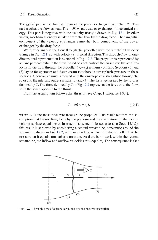
triangle in Fig. 12.1, so with velocity v 1 in axial direction. The through-flow in onedimensional representation is sketched in Fig. 12.2. The propeller is represented by
a plane perpendicular to the flow. Based on continuity of the mass flow, the axial velocity in the flow through the propeller ( v 1 = v 2 ) remains constant. Sections (0) and
(3) lay so far upstream and downstream that there is atmospheric pressure in these
sections. A control volume is formed with the envelope of a streamtube through the
rotor and the inlet and outlet sections (0) and (3). The thrust generated by the rotor is
denoted by T. The force denoted by T in Fig 12.2 represents the force onto the flow,
so in the sense opposite to the thrust.
From the assumptions follows that thrust is (see Chap. 1, Exercise 1.9.4):
(12.1)
where
m is the mass flow rate through the propeller. This result requires the assumption that the resulting force by the pressure and the shear stress on the control
volume surface equals zero. In case of absence of losses (see also Sect. 12.1.2),
this result is achieved by considering a second streamtube, concentric around the
streamtube drawn in Fig. 12.2, with an envelope so far from the propeller that the
pressure on it equals atmospheric pressure. As there is no work within the second
streamtube, the inflow and outflow velocities thus equal v 0 . The consequence is that
T m v v
=
−
(
),
3
0
Fig. 12.2 Through-flow of a propeller in one-dimensional representation
12.1 Thrust Generation
The dD w
. 1 part is the dissipated part of the power exchanged (see Chap. 2). This
part reaches the flow as heat. The −dD v
. 1 part causes exchange of mechanical energy. This part is negative with the velocity triangle drawn in Fig. 12.1. In other
words, mechanical energy is taken from the flow by the drag force. The tangential
component of the velocity v 1 changes somewhat both components of the power
exchanged by the drag force.
We further analyse the flow through the propeller with the simplified velocity
triangle in Fig. 12.1, so with velocity v 1 in axial direction. The through-flow in onedimensional representation is sketched in Fig. 12.2. The propeller is represented by
a plane perpendicular to the flow. Based on continuity of the mass flow, the axial velocity in the flow through the propeller ( v 1 = v 2 ) remains constant. Sections (0) and
(3) lay so far upstream and downstream that there is atmospheric pressure in these
sections. A control volume is formed with the envelope of a streamtube through the
rotor and the inlet and outlet sections (0) and (3). The thrust generated by the rotor is
denoted by T. The force denoted by T in Fig 12.2 represents the force onto the flow,
so in the sense opposite to the thrust.
From the assumptions follows that thrust is (see Chap. 1, Exercise 1.9.4):
(12.1)
where
m is the mass flow rate through the propeller. This result requires the assumption that the resulting force by the pressure and the shear stress on the control
volume surface equals zero. In case of absence of losses (see also Sect. 12.1.2),
this result is achieved by considering a second streamtube, concentric around the
streamtube drawn in Fig. 12.2, with an envelope so far from the propeller that the
pressure on it equals atmospheric pressure. As there is no work within the second
streamtube, the inflow and outflow velocities thus equal v 0 . The consequence is that
T m v v
=
−
(
),
3
0
Fig. 12.2 Through-flow of a propeller in one-dimensional representation