

420
12 Thrust Gas Turbines
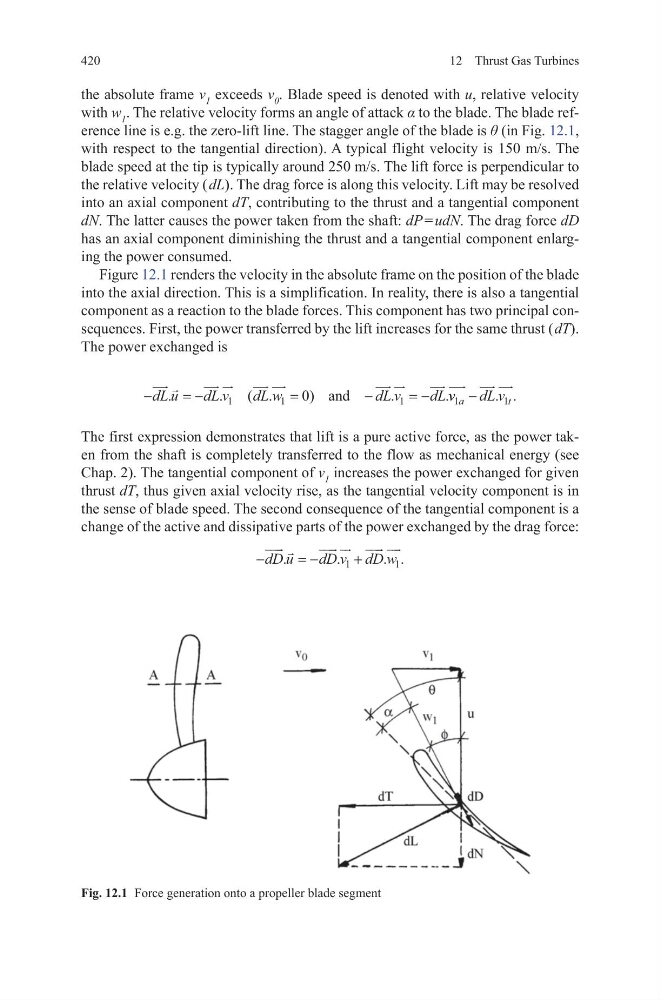
the absolute frame v 1 exceeds v 0 . Blade speed is denoted with u, relative velocity
with w 1 . The relative velocity forms an angle of attack α to the blade. The blade reference line is e.g. the zero-lift line. The stagger angle of the blade is θ (in Fig. 12.1,
with respect to the tangential direction). A typical flight velocity is 150 m/s. The
blade speed at the tip is typically around 250 m/s. The lift force is perpendicular to
the relative velocity ( dL). The drag force is along this velocity. Lift may be resolved
into an axial component dT, contributing to the thrust and a tangential component
dN. The latter causes the power taken from the shaft: dP = udN. The drag force dD
has an axial component diminishing the thrust and a tangential component enlarging the power consumed.
Figure 12.1 renders the velocity in the absolute frame on the position of the blade
into the axial direction. This is a simplification. In reality, there is also a tangential
component as a reaction to the blade forces. This component has two principal consequences. First, the power transferred by the lift increases for the same thrust ( dT).
The power exchanged is
The first expression demonstrates that lift is a pure active force, as the power taken from the shaft is completely transferred to the flow as mechanical energy (see
Chap. 2). The tangential component of v 1 increases the power exchanged for given
thrust dT, thus given axial velocity rise, as the tangential velocity component is in
the sense of blade speed. The second consequence of the tangential component is a
change of the active and dissipative parts of the power exchanged by the drag force:
−
=−
=
−
=−
dL u
dL v
dL w
d L v
dL
.
.
( .
)
.
.
1
1
1
0 and
v v
dL v
a
t
1
1
− . .
−
=−
+
dD u
dD v dD w
.
.
. .
1
1
Fig. 12.1 Force generation onto a propeller blade segment
12 Thrust Gas Turbines
the absolute frame v 1 exceeds v 0 . Blade speed is denoted with u, relative velocity
with w 1 . The relative velocity forms an angle of attack α to the blade. The blade reference line is e.g. the zero-lift line. The stagger angle of the blade is θ (in Fig. 12.1,
with respect to the tangential direction). A typical flight velocity is 150 m/s. The
blade speed at the tip is typically around 250 m/s. The lift force is perpendicular to
the relative velocity ( dL). The drag force is along this velocity. Lift may be resolved
into an axial component dT, contributing to the thrust and a tangential component
dN. The latter causes the power taken from the shaft: dP = udN. The drag force dD
has an axial component diminishing the thrust and a tangential component enlarging the power consumed.
Figure 12.1 renders the velocity in the absolute frame on the position of the blade
into the axial direction. This is a simplification. In reality, there is also a tangential
component as a reaction to the blade forces. This component has two principal consequences. First, the power transferred by the lift increases for the same thrust ( dT).
The power exchanged is
The first expression demonstrates that lift is a pure active force, as the power taken from the shaft is completely transferred to the flow as mechanical energy (see
Chap. 2). The tangential component of v 1 increases the power exchanged for given
thrust dT, thus given axial velocity rise, as the tangential velocity component is in
the sense of blade speed. The second consequence of the tangential component is a
change of the active and dissipative parts of the power exchanged by the drag force:
−
=−
=
−
=−
dL u
dL v
dL w
d L v
dL
.
.
( .
)
.
.
1
1
1
0 and
v v
dL v
a
t
1
1
− . .
−
=−
+
dD u
dD v dD w
.
.
. .
1
1
Fig. 12.1 Force generation onto a propeller blade segment