

374
11 Power Gas Turbines
electric power (order of several tens of MW). Typical plants are off-shore oil or
gas platforms, desalination plants and refineries. These machines are also used for
mechanical drive of compressors and pumps in such plants. Adapted machines for
ship propulsion exist (see the websites; search for Rolls Royce or General Electric,
in combination with the term marine gas turbines). Manufacturers of gas turbines
for power generation typically also offer heavy duty machines of smaller power
for electricity generation in industrial plants or mechanical drive (search for small
heavy duty gas turbines) and there are manufacturers who only make such smaller
machines (e.g. MAN Diesel and Turbo).
11.1.4 Compressor Part
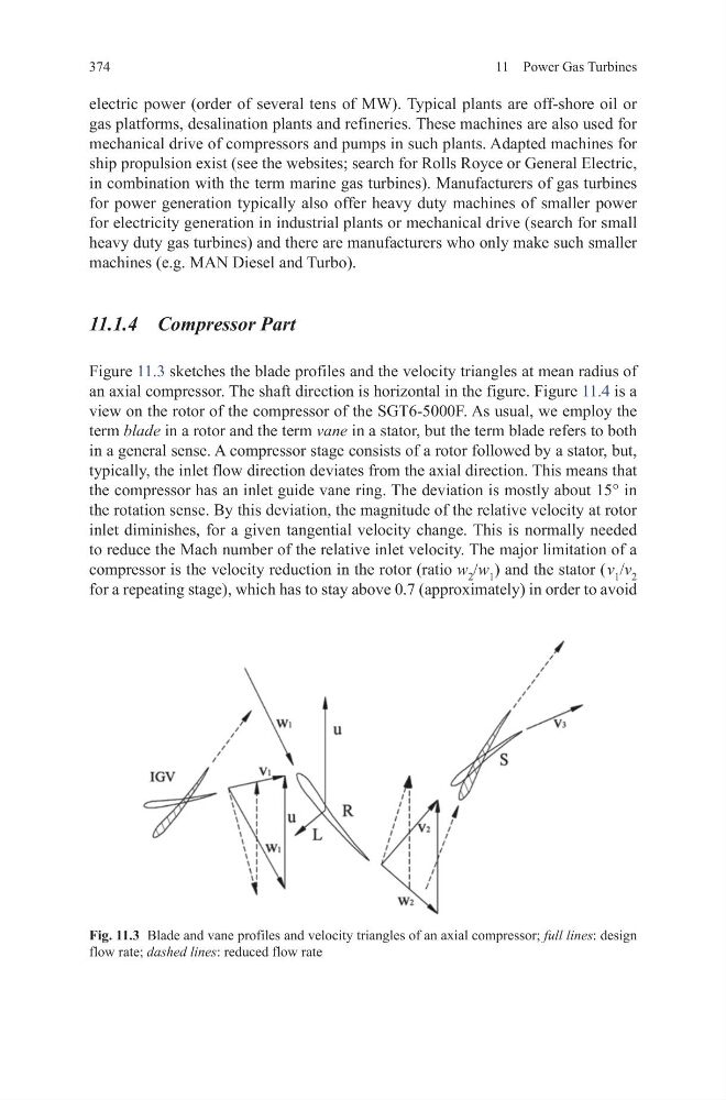
Figure 11.3 sketches the blade profiles and the velocity triangles at mean radius of
an axial compressor. The shaft direction is horizontal in the figure. Figure 11.4 is a
view on the rotor of the compressor of the SGT6-5000F. As usual, we employ the
term blade in a rotor and the term vane in a stator, but the term blade refers to both
in a general sense. A compressor stage consists of a rotor followed by a stator, but,
typically, the inlet flow direction deviates from the axial direction. This means that
the compressor has an inlet guide vane ring. The deviation is mostly about 15° in
the rotation sense. By this deviation, the magnitude of the relative velocity at rotor
inlet diminishes, for a given tangential velocity change. This is normally needed
to reduce the Mach number of the relative inlet velocity. The major limitation of a
compressor is the velocity reduction in the rotor (ratio w 2 /w 1 ) and the stator ( v 1 /v 2
for a repeating stage), which has to stay above 0.7 (approximately) in order to avoid
Fig. 11.3 Blade and vane profiles and velocity triangles of an axial compressor; full lines: design
flow rate; dashed lines: reduced flow rate
11 Power Gas Turbines
electric power (order of several tens of MW). Typical plants are off-shore oil or
gas platforms, desalination plants and refineries. These machines are also used for
mechanical drive of compressors and pumps in such plants. Adapted machines for
ship propulsion exist (see the websites; search for Rolls Royce or General Electric,
in combination with the term marine gas turbines). Manufacturers of gas turbines
for power generation typically also offer heavy duty machines of smaller power
for electricity generation in industrial plants or mechanical drive (search for small
heavy duty gas turbines) and there are manufacturers who only make such smaller
machines (e.g. MAN Diesel and Turbo).
11.1.4 Compressor Part
Figure 11.3 sketches the blade profiles and the velocity triangles at mean radius of
an axial compressor. The shaft direction is horizontal in the figure. Figure 11.4 is a
view on the rotor of the compressor of the SGT6-5000F. As usual, we employ the
term blade in a rotor and the term vane in a stator, but the term blade refers to both
in a general sense. A compressor stage consists of a rotor followed by a stator, but,
typically, the inlet flow direction deviates from the axial direction. This means that
the compressor has an inlet guide vane ring. The deviation is mostly about 15° in
the rotation sense. By this deviation, the magnitude of the relative velocity at rotor
inlet diminishes, for a given tangential velocity change. This is normally needed
to reduce the Mach number of the relative inlet velocity. The major limitation of a
compressor is the velocity reduction in the rotor (ratio w 2 /w 1 ) and the stator ( v 1 /v 2
for a repeating stage), which has to stay above 0.7 (approximately) in order to avoid
Fig. 11.3 Blade and vane profiles and velocity triangles of an axial compressor; full lines: design
flow rate; dashed lines: reduced flow rate