

375
11.1 General Concept and Components
flow separation. The consequence is that the flow turning in both stator and rotor is
limited, which limits the work coefficient (
2
/
W u
y = ∆
, thus
/
/
u
u
w u
v u
y = ∆
= ∆
)
to about 0.4 on the mean radius. Therefore, the blade speed is chosen as high as
possible. In a heavy duty machine, it is typically somewhat less than 300 m/s on
the mean radius (say 280–300 m/s). The precise value depends on the size of the
machine and the rotational speed (300 m/s corresponds to a diameter of 1.91 m at
3000 rpm). The blade speed is near to the sonic speed, but below it (in air at 288 K,
the speed of sound is 340 m/s). The inlet velocity of the rotor is approximately the
same (Mach number around 0.85). So, the limitation of the blade speed comes from
keeping inflow velocities just subsonic and is not caused by strength limitations
(for more detailed discussion, see Chap. 13). The vanes and blades in a compressor
are commonly made of alloys of steel with chromium and cobalt. With respect to
strength, the blade speed at mean radius may be close to 400 m/s. The magnitude of
the stage work is quite sensitive to the choice of the blade speed. With 280 m/s corresponds about 30 kJ/kg, but with 300 m/s it is already about 36 kJ/kg. A pressure
ratio of 17 starting with air at 288 K requires about 420 kJ/kg. This means 14 stages
of 30 kJ/kg. A pressure ratio of 20 requires about 460 kJ/kg and can be realised with
13 stages of 36 kJ/kg.
Usually, the angular position of the inlet guide vanes of a compressor can be
adjusted to adapt the machine to lower mass flow rate than the design mass flow
rate. The SGT6-5000F of Fig. 11.2 has an adjustable guide vane ring. A close look
at the figure reveals the pivot of the vane in the upper position, linked by a lever
arm to a ring, allowing collective adjustment of the vane angles. With some compressors also the stator vane angles of a number of stages at the front are adjustable,
up to about one fourth of the total number of stages (typically three or four stages).
Such stages are often called variable geometry stages. The SGT6-5000F shown
in Fig. 11.2 only has adjustable inlet vanes, but the most recent version has three
rows of variable stators. With variable geometry front stages, the compressor may
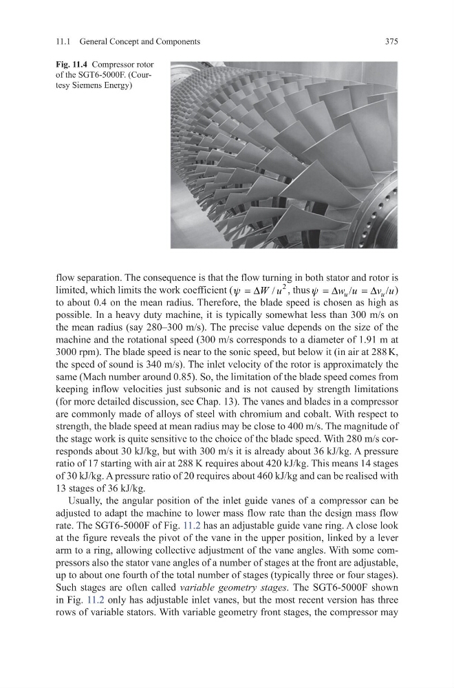
Fig. 11.4 Compressor rotor
of the SGT6-5000F. (Courtesy Siemens Energy)
11.1 General Concept and Components
flow separation. The consequence is that the flow turning in both stator and rotor is
limited, which limits the work coefficient (
2
/
W u
y = ∆
, thus
/
/
u
u
w u
v u
y = ∆
= ∆
)
to about 0.4 on the mean radius. Therefore, the blade speed is chosen as high as
possible. In a heavy duty machine, it is typically somewhat less than 300 m/s on
the mean radius (say 280–300 m/s). The precise value depends on the size of the
machine and the rotational speed (300 m/s corresponds to a diameter of 1.91 m at
3000 rpm). The blade speed is near to the sonic speed, but below it (in air at 288 K,
the speed of sound is 340 m/s). The inlet velocity of the rotor is approximately the
same (Mach number around 0.85). So, the limitation of the blade speed comes from
keeping inflow velocities just subsonic and is not caused by strength limitations
(for more detailed discussion, see Chap. 13). The vanes and blades in a compressor
are commonly made of alloys of steel with chromium and cobalt. With respect to
strength, the blade speed at mean radius may be close to 400 m/s. The magnitude of
the stage work is quite sensitive to the choice of the blade speed. With 280 m/s corresponds about 30 kJ/kg, but with 300 m/s it is already about 36 kJ/kg. A pressure
ratio of 17 starting with air at 288 K requires about 420 kJ/kg. This means 14 stages
of 30 kJ/kg. A pressure ratio of 20 requires about 460 kJ/kg and can be realised with
13 stages of 36 kJ/kg.
Usually, the angular position of the inlet guide vanes of a compressor can be
adjusted to adapt the machine to lower mass flow rate than the design mass flow
rate. The SGT6-5000F of Fig. 11.2 has an adjustable guide vane ring. A close look
at the figure reveals the pivot of the vane in the upper position, linked by a lever
arm to a ring, allowing collective adjustment of the vane angles. With some compressors also the stator vane angles of a number of stages at the front are adjustable,
up to about one fourth of the total number of stages (typically three or four stages).
Such stages are often called variable geometry stages. The SGT6-5000F shown
in Fig. 11.2 only has adjustable inlet vanes, but the most recent version has three
rows of variable stators. With variable geometry front stages, the compressor may
Fig. 11.4 Compressor rotor
of the SGT6-5000F. (Courtesy Siemens Energy)