

364
10 Wind Turbines
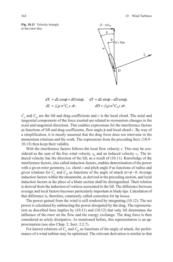
C L and C D are the lift and drag coefficients and c is the local chord. The axial and
tangential components of the force exerted are related to momentum changes in the
axial and tangential directions. This enables expressions for the interference factors
as functions of lift and drag coefficients, flow angle ϕ and local chord c. By way of
a simplification, it is mostly assumed that the drag force does not intervene in the
momentum relations and the work. The expressions from the preceding Sect. (10.9–
10.13) then keep their validity.
With the interference factors follows the local flow velocity v. This may be considered as the sum of the free wind velocity v 0 and an induced velocity v i . The induced velocity has the direction of the lift, as a result of (10.11). Knowledge of the
interference factors, also called induction factors, enables determination of the power
with a given rotor geometry, i.e. chord c and pitch angle θ as functions of radius and
given relations for C L and C D as functions of the angle of attack a = ϕ − θ. Average
induction factors within the streamtube, as derived in the preceding section, and local
induction factors at the place of a blade section shall be distinguished. Their relation
is derived from the induction of vortices associated to the lift. The difference between
average and local factors becomes particularly important at blade tips. Calculation of
that difference is, therefore, commonly called correction for tip losses.
The power gained from the wind is still rendered by integrating (10.12). The net
power is calculated by subtracting the power dissipated by the drag. The representation as described here implies by (10.11) and (10.12) that only lift determines the
influence of the rotor on the flow and the energy exchange. The drag force is then
considered as solely dissipative. As mentioned before, this representation is an approximation (see also Chap. 2, Sect. 2.2.7).
For known relations of C L and C D as functions of the angle of attack, the performance of a wind turbine may be optimised. The relevant derivation is similar to that
2
2
1
1
2
2
cos
sin
sin
cos
.
L
D
dX dL
dD
, dY dL
dD
,
dL
w C c dr,
dD
w C c dr
f
f
f
f
r
r
=
+
=
−
=
=
Fig. 10.11 Velocity triangle
at the rotor disc
10 Wind Turbines
C L and C D are the lift and drag coefficients and c is the local chord. The axial and
tangential components of the force exerted are related to momentum changes in the
axial and tangential directions. This enables expressions for the interference factors
as functions of lift and drag coefficients, flow angle ϕ and local chord c. By way of
a simplification, it is mostly assumed that the drag force does not intervene in the
momentum relations and the work. The expressions from the preceding Sect. (10.9–
10.13) then keep their validity.
With the interference factors follows the local flow velocity v. This may be considered as the sum of the free wind velocity v 0 and an induced velocity v i . The induced velocity has the direction of the lift, as a result of (10.11). Knowledge of the
interference factors, also called induction factors, enables determination of the power
with a given rotor geometry, i.e. chord c and pitch angle θ as functions of radius and
given relations for C L and C D as functions of the angle of attack a = ϕ − θ. Average
induction factors within the streamtube, as derived in the preceding section, and local
induction factors at the place of a blade section shall be distinguished. Their relation
is derived from the induction of vortices associated to the lift. The difference between
average and local factors becomes particularly important at blade tips. Calculation of
that difference is, therefore, commonly called correction for tip losses.
The power gained from the wind is still rendered by integrating (10.12). The net
power is calculated by subtracting the power dissipated by the drag. The representation as described here implies by (10.11) and (10.12) that only lift determines the
influence of the rotor on the flow and the energy exchange. The drag force is then
considered as solely dissipative. As mentioned before, this representation is an approximation (see also Chap. 2, Sect. 2.2.7).
For known relations of C L and C D as functions of the angle of attack, the performance of a wind turbine may be optimised. The relevant derivation is similar to that
2
2
1
1
2
2
cos
sin
sin
cos
.
L
D
dX dL
dD
, dY dL
dD
,
dL
w C c dr,
dD
w C c dr
f
f
f
f
r
r
=
+
=
−
=
=
Fig. 10.11 Velocity triangle
at the rotor disc