

363
10.3 Wind Turbine Performance Analysis
Expressions (10.11) and (10.13) together determine the optimal variation of the factors a and b as functions of r
l . The solution is (10.11), together with
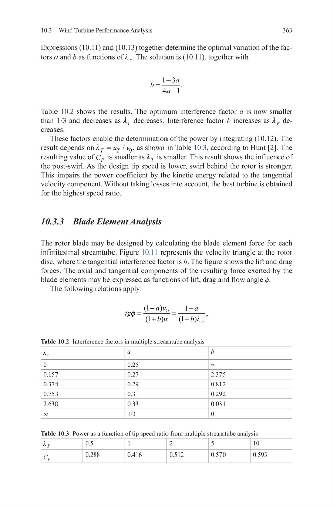
Table 10.2 shows the results. The optimum interference factor a is now smaller
than 1/3 and decreases as r
l decreases. Interference factor b increases as r
l decreases.
These factors enable the determination of the power by integrating (10.12). The
result depends on
0
/ ,
T
T
u v
l =
as shown in Table 10.3, according to Hunt [2]. The
resulting value of C P is smaller as T
l is smaller. This result shows the influence of
the post-swirl. As the design tip speed is lower, swirl behind the rotor is stronger.
This impairs the power coefficient by the kinetic energy related to the tangential
velocity component. Without taking losses into account, the best turbine is obtained
for the highest speed ratio.
10.3.3 Blade Element Analysis
The rotor blade may be designed by calculating the blade element force for each
infinitesimal streamtube. Figure 10.11 represents the velocity triangle at the rotor
disc, where the tangential interference factor is b. The figure shows the lift and drag
forces. The axial and tangential components of the resulting force exerted by the
blade elements may be expressed as functions of lift, drag and flow angle ϕ.
The following relations apply:
b
a
a
=
−
−
1 3
4 1
.
0
(1 )
1
,
(1 )
(1 ) r
a v
a
tg
b u
b
f
l
−
−
=
=
+
+
Table 10.2 Interference factors in multiple streamtube analysis
r
l
a
b
0
0.25
∞
0.157
0.27
2.375
0.374
0.29
0.812
0.753
0.31
0.292
2.630
0.33
0.031
∞
1/3
0
Table 10.3 Power as a function of tip speed ratio from multiple streamtube analysis
T
l
0.5
1
2
5
10
C P
0.288
0.416
0.512
0.570
0.593
10.3 Wind Turbine Performance Analysis
Expressions (10.11) and (10.13) together determine the optimal variation of the factors a and b as functions of r
l . The solution is (10.11), together with
Table 10.2 shows the results. The optimum interference factor a is now smaller
than 1/3 and decreases as r
l decreases. Interference factor b increases as r
l decreases.
These factors enable the determination of the power by integrating (10.12). The
result depends on
0
/ ,
T
T
u v
l =
as shown in Table 10.3, according to Hunt [2]. The
resulting value of C P is smaller as T
l is smaller. This result shows the influence of
the post-swirl. As the design tip speed is lower, swirl behind the rotor is stronger.
This impairs the power coefficient by the kinetic energy related to the tangential
velocity component. Without taking losses into account, the best turbine is obtained
for the highest speed ratio.
10.3.3 Blade Element Analysis
The rotor blade may be designed by calculating the blade element force for each
infinitesimal streamtube. Figure 10.11 represents the velocity triangle at the rotor
disc, where the tangential interference factor is b. The figure shows the lift and drag
forces. The axial and tangential components of the resulting force exerted by the
blade elements may be expressed as functions of lift, drag and flow angle ϕ.
The following relations apply:
b
a
a
=
−
−
1 3
4 1
.
0
(1 )
1
,
(1 )
(1 ) r
a v
a
tg
b u
b
f
l
−
−
=
=
+
+
Table 10.2 Interference factors in multiple streamtube analysis
r
l
a
b
0
0.25
∞
0.157
0.27
2.375
0.374
0.29
0.812
0.753
0.31
0.292
2.630
0.33
0.031
∞
1/3
0
Table 10.3 Power as a function of tip speed ratio from multiple streamtube analysis
T
l
0.5
1
2
5
10
C P
0.288
0.416
0.512
0.570
0.593