

9 Hydraulic Turbines
328
9.3.3 Determination of the Main Dimensions
Flow rate and head are imposed by the application. Specific speed is chosen with
regard to the strength limitations from the centrifugal load. Specific speed is mostly
chosen as high as possible in order to achieve relatively high and electrically serviceable rotational speeds (428, 500, 600 rpm). With a relatively high flow rate,
several rotors and several injectors may be needed. The jet velocity follows from
where ϕ s = 0.96–0.98. The diameter of the injector throat follows from:
with Q the flow rate per injector. All bucket dimensions are subsequently derived
from the jet diameter. The condition for maximum efficiency,
1
u / v 0.48,
≈
determines the blade speed and thus the rotor diameter. The number of blades depends
on the condition that at least one blade must receive the jet. When a blade leaves the
jet, the following one shall have entered with some overlap.
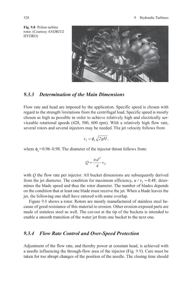
Figure 9.8 shows a rotor. Rotors are mostly manufactured of stainless steel because of good resistance of this material to erosion. Other erosion-exposed parts are
made of stainless steel as well. The cut-out at the tip of the buckets is intended to
enable a smooth transition of the water jet from one bucket to the next one.
9.3.4 Flow Rate Control and Over-Speed Protection
Adjustment of the flow rate, and thereby power at constant head, is achieved with
a needle influencing the through-flow area of the injector (Fig. 9.9). Care must be
taken for too abrupt changes of the position of the needle. The closing time should
v
g H
s
1
2
= φ
,
Q
d v
=
π
2
1
4
,
Fig. 9.8 Pelton turbine
rotor. (Courtesy ANDRITZ
HYDRO)
328
9.3.3 Determination of the Main Dimensions
Flow rate and head are imposed by the application. Specific speed is chosen with
regard to the strength limitations from the centrifugal load. Specific speed is mostly
chosen as high as possible in order to achieve relatively high and electrically serviceable rotational speeds (428, 500, 600 rpm). With a relatively high flow rate,
several rotors and several injectors may be needed. The jet velocity follows from
where ϕ s = 0.96–0.98. The diameter of the injector throat follows from:
with Q the flow rate per injector. All bucket dimensions are subsequently derived
from the jet diameter. The condition for maximum efficiency,
1
u / v 0.48,
≈
determines the blade speed and thus the rotor diameter. The number of blades depends
on the condition that at least one blade must receive the jet. When a blade leaves the
jet, the following one shall have entered with some overlap.
Figure 9.8 shows a rotor. Rotors are mostly manufactured of stainless steel because of good resistance of this material to erosion. Other erosion-exposed parts are
made of stainless steel as well. The cut-out at the tip of the buckets is intended to
enable a smooth transition of the water jet from one bucket to the next one.
9.3.4 Flow Rate Control and Over-Speed Protection
Adjustment of the flow rate, and thereby power at constant head, is achieved with
a needle influencing the through-flow area of the injector (Fig. 9.9). Care must be
taken for too abrupt changes of the position of the needle. The closing time should
v
g H
s
1
2
= φ
,
Q
d v
=
π
2
1
4
,
Fig. 9.8 Pelton turbine
rotor. (Courtesy ANDRITZ
HYDRO)