

9.4 Francis and Kaplan Turbines: Reaction Turbines
329
be sufficiently long (typically 15–30 s) in order to avoid water hammer in the supply
duct. If a fast flow rate reduction is required with a sudden turbine load decrease, a
jet deflector is used. The deflector is turned between the injector and the buckets.
This takes at most a few seconds. The deflected jet causes strong erosion of the surrounding parts. This device should thus only be applied in anticipation of flow rate
adjustment by a slow movement of the needle.
9.4 Francis and Kaplan Turbines: Reaction Turbines
9.4.1 Shape of the Velocity Triangles: Kinematic
Parameters
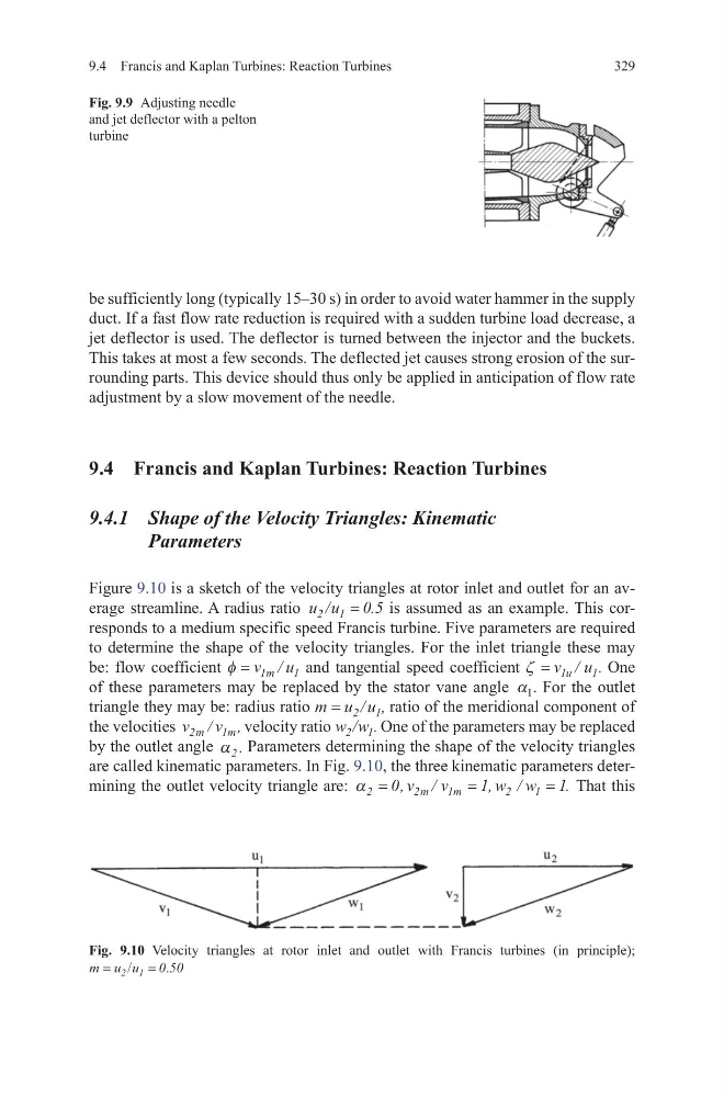
Figure 9.10 is a sketch of the velocity triangles at rotor inlet and outlet for an average streamline. A radius ratio u u
2 1
0 5
/
.
=
is assumed as an example. This corresponds to a medium specific speed Francis turbine. Five parameters are required
to determine the shape of the velocity triangles. For the inlet triangle these may
be: flow coefficient φ = v u
m
1
1
/ and tangential speed coefficient ζ = v u
u
1
1
/ . One
of these parameters may be replaced by the stator vane angle α 1 . For the outlet
triangle they may be: radius ratio m u u
= 2 1
/ , ratio of the meridional component of
the velocities v
v
m
m
2
1
/
, velocity ratio w w
2 1
/ . One of the parameters may be replaced
by the outlet angle α 2 . Parameters determining the shape of the velocity triangles
are called kinematic parameters. In Fig. 9.10, the three kinematic parameters determining the outlet velocity triangle are: α 2
2
1
2
1
0
1
1
=
=
=
,
/
,
/
.
v
v
w w
m
m
That this
Fig. 9.10 Velocity triangles at rotor inlet and outlet with Francis turbines (in principle);
m u u
= = 2 1 0 50
/
.
Fig. 9.9 Adjusting needle
and jet deflector with a pelton
turbine
329
be sufficiently long (typically 15–30 s) in order to avoid water hammer in the supply
duct. If a fast flow rate reduction is required with a sudden turbine load decrease, a
jet deflector is used. The deflector is turned between the injector and the buckets.
This takes at most a few seconds. The deflected jet causes strong erosion of the surrounding parts. This device should thus only be applied in anticipation of flow rate
adjustment by a slow movement of the needle.
9.4 Francis and Kaplan Turbines: Reaction Turbines
9.4.1 Shape of the Velocity Triangles: Kinematic
Parameters
Figure 9.10 is a sketch of the velocity triangles at rotor inlet and outlet for an average streamline. A radius ratio u u
2 1
0 5
/
.
=
is assumed as an example. This corresponds to a medium specific speed Francis turbine. Five parameters are required
to determine the shape of the velocity triangles. For the inlet triangle these may
be: flow coefficient φ = v u
m
1
1
/ and tangential speed coefficient ζ = v u
u
1
1
/ . One
of these parameters may be replaced by the stator vane angle α 1 . For the outlet
triangle they may be: radius ratio m u u
= 2 1
/ , ratio of the meridional component of
the velocities v
v
m
m
2
1
/
, velocity ratio w w
2 1
/ . One of the parameters may be replaced
by the outlet angle α 2 . Parameters determining the shape of the velocity triangles
are called kinematic parameters. In Fig. 9.10, the three kinematic parameters determining the outlet velocity triangle are: α 2
2
1
2
1
0
1
1
=
=
=
,
/
,
/
.
v
v
w w
m
m
That this
Fig. 9.10 Velocity triangles at rotor inlet and outlet with Francis turbines (in principle);
m u u
= = 2 1 0 50
/
.
Fig. 9.9 Adjusting needle
and jet deflector with a pelton
turbine