

9.3 Pelton Turbines: Impulse Turbines
327
The rotational speed is derived from the blade speed by
Thus: Ω
Ω
s
s
Q
gH
u
gH
d
D
=
=
(
)
.
3 4
3 4
2
2
φ π
With the optimum speed ratio λ = u
gH
/ 2
of about 0.48 and φ s
97
= 0. :
(9.2)
For best flow conditions, the d/D value lies between about 1/16 and 1/8. Small d/D
values generate long jets with a large contact surface with the air compared to the
cross section. This causes a relatively high friction and drop formation. High d/D
values generate jets with bad flow guidance by the buckets. In practice d/D can vary
from about 1/24 to 1/8, with low d/D values resulting in machines with a lower efficiency.
There is a constructional limit to the specific speed because of the centrifugal
load on the buckets. With increasing s
W at constant Q and H values, Ω must increase. The centrifugal force on a bucket is mΩ
2
r. The mass of the bucket ( m) stays
constant since the mass only depends on d, so on Q and v 1 , which both are constant. Further u = Ω r must be constant, as v 1 is constant and u v
/ 1 as well. The centrifugal force is thus proportional to Ω. If s
W increases, D must decrease, because
of s ~ d D
W
. The machine diameter D cannot decrease below a minimum value
determined by the circumferential length required for mounting the buckets since
their size and number are determined by flow requirements. The required mounting length increases with the head, as forces on the buckets increase proportionally
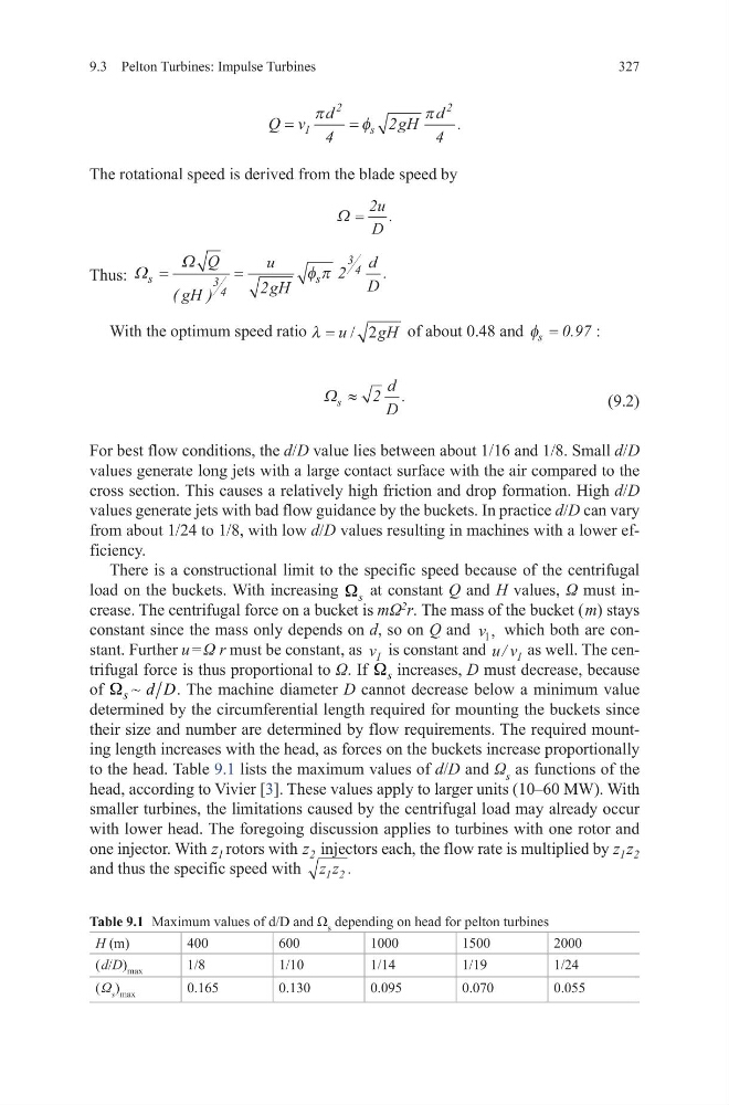
to the head. Table 9.1 lists the maximum values of d/D and Ω s as functions of the
head, according to Vivier [3]. These values apply to larger units (10–60 MW). With
smaller turbines, the limitations caused by the centrifugal load may already occur
with lower head. The foregoing discussion applies to turbines with one rotor and
one injector. With z 1 rotors with z 2 injectors each, the flow rate is multiplied by z z
1 2
and thus the specific speed with z z
1 2 .
Q v
d
gH
d
s
=
=
1
2
2
4
2
4
π
φ
π .
Ω =
2u
D
.
Ω s
d
D
≈ 2 .
Table 9.1 Maximum values of d/D and Ω s depending on head for pelton turbines
H (m)
400
600
1000
1500
2000
( d/D) max
1/8
1/10
1/14
1/19
1/24
( Ω s ) max
0.165
0.130
0.095
0.070
0.055
327
The rotational speed is derived from the blade speed by
Thus: Ω
Ω
s
s
Q
gH
u
gH
d
D
=
=
(
)
.
3 4
3 4
2
2
φ π
With the optimum speed ratio λ = u
gH
/ 2
of about 0.48 and φ s
97
= 0. :
(9.2)
For best flow conditions, the d/D value lies between about 1/16 and 1/8. Small d/D
values generate long jets with a large contact surface with the air compared to the
cross section. This causes a relatively high friction and drop formation. High d/D
values generate jets with bad flow guidance by the buckets. In practice d/D can vary
from about 1/24 to 1/8, with low d/D values resulting in machines with a lower efficiency.
There is a constructional limit to the specific speed because of the centrifugal
load on the buckets. With increasing s
W at constant Q and H values, Ω must increase. The centrifugal force on a bucket is mΩ
2
r. The mass of the bucket ( m) stays
constant since the mass only depends on d, so on Q and v 1 , which both are constant. Further u = Ω r must be constant, as v 1 is constant and u v
/ 1 as well. The centrifugal force is thus proportional to Ω. If s
W increases, D must decrease, because
of s ~ d D
W
. The machine diameter D cannot decrease below a minimum value
determined by the circumferential length required for mounting the buckets since
their size and number are determined by flow requirements. The required mounting length increases with the head, as forces on the buckets increase proportionally
to the head. Table 9.1 lists the maximum values of d/D and Ω s as functions of the
head, according to Vivier [3]. These values apply to larger units (10–60 MW). With
smaller turbines, the limitations caused by the centrifugal load may already occur
with lower head. The foregoing discussion applies to turbines with one rotor and
one injector. With z 1 rotors with z 2 injectors each, the flow rate is multiplied by z z
1 2
and thus the specific speed with z z
1 2 .
Q v
d
gH
d
s
=
=
1
2
2
4
2
4
π
φ
π .
Ω =
2u
D
.
Ω s
d
D
≈ 2 .
Table 9.1 Maximum values of d/D and Ω s depending on head for pelton turbines
H (m)
400
600
1000
1500
2000
( d/D) max
1/8
1/10
1/14
1/19
1/24
( Ω s ) max
0.165
0.130
0.095
0.070
0.055