

9 Hydraulic Turbines
326
Overall (global) efficiency is η η η η
g
s r m
=
.
From the foregoing values and a mechanical efficiency of about 0.98, it follows
that the overall efficiency at optimum speed ratio is about 0.90. It even might be
better in practice, namely up to 0.92.
Rotor power is P
m W
rot = ∆ .
Shaft power P shaft equals rotor power multiplied by mechanical efficiency.
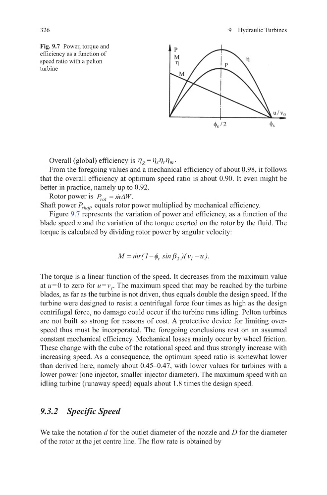
Figure 9.7 represents the variation of power and efficiency, as a function of the
blade speed u and the variation of the torque exerted on the rotor by the fluid. The
torque is calculated by dividing rotor power by angular velocity:
The torque is a linear function of the speed. It decreases from the maximum value
at u = 0 to zero for u = v 1 . The maximum speed that may be reached by the turbine
blades, as far as the turbine is not driven, thus equals double the design speed. If the
turbine were designed to resist a centrifugal force four times as high as the design
centrifugal force, no damage could occur if the turbine runs idling. Pelton turbines
are not built so strong for reasons of cost. A protective device for limiting overspeed thus must be incorporated. The foregoing conclusions rest on an assumed
constant mechanical efficiency. Mechanical losses mainly occur by wheel friction.
These change with the cube of the rotational speed and thus strongly increase with
increasing speed. As a consequence, the optimum speed ratio is somewhat lower
than derived here, namely about 0.45–0.47, with lower values for turbines with a
lower power (one injector, smaller injector diameter). The maximum speed with an
idling turbine (runaway speed) equals about 1.8 times the design speed.
9.3.2 Specific Speed
We take the notation d for the outlet diameter of the nozzle and D for the diameter
of the rotor at the jet centre line. The flow rate is obtained by
M mr
v u
r
=
−
−
(
sin )(
).
1
2
1
φ
β
Fig. 9.7 Power, torque and
efficiency as a function of
speed ratio with a pelton
turbine
326
Overall (global) efficiency is η η η η
g
s r m
=
.
From the foregoing values and a mechanical efficiency of about 0.98, it follows
that the overall efficiency at optimum speed ratio is about 0.90. It even might be
better in practice, namely up to 0.92.
Rotor power is P
m W
rot = ∆ .
Shaft power P shaft equals rotor power multiplied by mechanical efficiency.
Figure 9.7 represents the variation of power and efficiency, as a function of the
blade speed u and the variation of the torque exerted on the rotor by the fluid. The
torque is calculated by dividing rotor power by angular velocity:
The torque is a linear function of the speed. It decreases from the maximum value
at u = 0 to zero for u = v 1 . The maximum speed that may be reached by the turbine
blades, as far as the turbine is not driven, thus equals double the design speed. If the
turbine were designed to resist a centrifugal force four times as high as the design
centrifugal force, no damage could occur if the turbine runs idling. Pelton turbines
are not built so strong for reasons of cost. A protective device for limiting overspeed thus must be incorporated. The foregoing conclusions rest on an assumed
constant mechanical efficiency. Mechanical losses mainly occur by wheel friction.
These change with the cube of the rotational speed and thus strongly increase with
increasing speed. As a consequence, the optimum speed ratio is somewhat lower
than derived here, namely about 0.45–0.47, with lower values for turbines with a
lower power (one injector, smaller injector diameter). The maximum speed with an
idling turbine (runaway speed) equals about 1.8 times the design speed.
9.3.2 Specific Speed
We take the notation d for the outlet diameter of the nozzle and D for the diameter
of the rotor at the jet centre line. The flow rate is obtained by
M mr
v u
r
=
−
−
(
sin )(
).
1
2
1
φ
β
Fig. 9.7 Power, torque and
efficiency as a function of
speed ratio with a pelton
turbine