

9.3 Pelton Turbines: Impulse Turbines
325
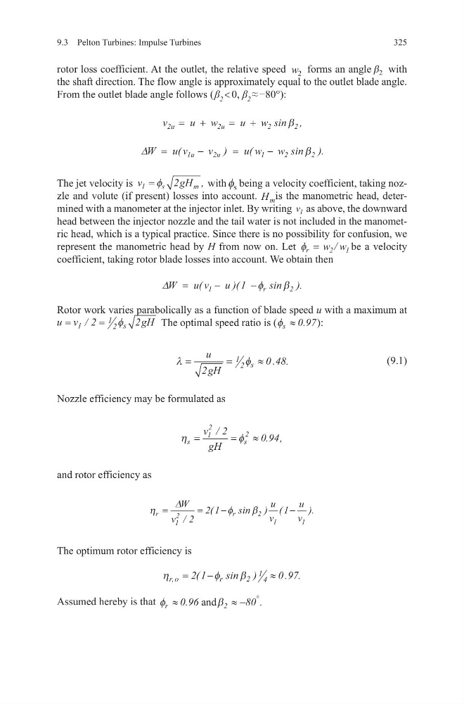
rotor loss coefficient. At the outlet, the relative speed w 2 forms an angle β 2 with
the shaft direction. The flow angle is approximately equal to the outlet blade angle.
From the outlet blade angle follows ( β 2 < 0, β 2 ≈ −80°):
The jet velocity is v
g H
s
m
1
2
= φ
, with φ s being a velocity coefficient, taking nozzle and volute (if present) losses into account. H m is the manometric head, determined with a manometer at the injector inlet. By writing v 1 as above, the downward
head between the injector nozzle and the tail water is not included in the manometric head, which is a typical practice. Since there is no possibility for confusion, we
represent the manometric head by H from now on. Let φ r w w
= 2 1
/ be a velocity
coefficient, taking rotor blade losses into account. We obtain then
Rotor work varies parabolically as a function of blade speed u with a maximum at
u v
gH
s
=
=
1
1 2
2
2
/
φ
The optimal speed ratio is (φ s ≈ 0.97):
(9.1)
Nozzle efficiency may be formulated as
and rotor efficiency as
The optimum rotor efficiency is
Assumed hereby is that φ
β
r
2
96
8
≈
≈−
°
0
0
.
.
and
v
u w
u w
2u
2u
2
2
= +
= +
sin ,
β
∆W
u v
v
u w
w
1u
2u
1
2
2
=
−
=
−
(
)
(
s in ).
β
∆W
u v
u 1
1
r
2
=
−
−
(
)(
sin ).
φ
β
λ
φ
=
=
≈
u
gH
s
2
0 48
1 2
. .
η
φ
s
s
v
gH
=
=
≈
1
2
2
2
0 94
/
. ,
η
φ
β
r
r
W
v
u
v
u
v
=
=
−
−
∆
1
2
2
1
1
2
2 1
1
/
(
sin ) (
).
η
φ
β
r o
r
,
(
sin )
. .
=
−
≈
2 1
0 97
2
1 4
325
rotor loss coefficient. At the outlet, the relative speed w 2 forms an angle β 2 with
the shaft direction. The flow angle is approximately equal to the outlet blade angle.
From the outlet blade angle follows ( β 2 < 0, β 2 ≈ −80°):
The jet velocity is v
g H
s
m
1
2
= φ
, with φ s being a velocity coefficient, taking nozzle and volute (if present) losses into account. H m is the manometric head, determined with a manometer at the injector inlet. By writing v 1 as above, the downward
head between the injector nozzle and the tail water is not included in the manometric head, which is a typical practice. Since there is no possibility for confusion, we
represent the manometric head by H from now on. Let φ r w w
= 2 1
/ be a velocity
coefficient, taking rotor blade losses into account. We obtain then
Rotor work varies parabolically as a function of blade speed u with a maximum at
u v
gH
s
=
=
1
1 2
2
2
/
φ
The optimal speed ratio is (φ s ≈ 0.97):
(9.1)
Nozzle efficiency may be formulated as
and rotor efficiency as
The optimum rotor efficiency is
Assumed hereby is that φ
β
r
2
96
8
≈
≈−
°
0
0
.
.
and
v
u w
u w
2u
2u
2
2
= +
= +
sin ,
β
∆W
u v
v
u w
w
1u
2u
1
2
2
=
−
=
−
(
)
(
s in ).
β
∆W
u v
u 1
1
r
2
=
−
−
(
)(
sin ).
φ
β
λ
φ
=
=
≈
u
gH
s
2
0 48
1 2
. .
η
φ
s
s
v
gH
=
=
≈
1
2
2
2
0 94
/
. ,
η
φ
β
r
r
W
v
u
v
u
v
=
=
−
−
∆
1
2
2
1
1
2
2 1
1
/
(
sin ) (
).
η
φ
β
r o
r
,
(
sin )
. .
=
−
≈
2 1
0 97
2
1 4