

9 Hydraulic Turbines
322
thus amount to 500, 427, 375 rpm, with lower rotational speeds as heads get lower.
With Pelton turbines, rotational speeds become impracticable at low heads, but, of
course, the smaller the turbine, the lower the head may be.
The example demonstrates the irrelevance of multi-stage hydraulic turbines and
shows that lower heads require much higher rotational speeds than with impulsetype machines. As we will study further, the relation between the degree of reaction
and the optimal speed ratio with hydraulic turbines is the same as with steam turbines. Lower heads thus require turbines with a medium degree of reaction (Francis turbine). Still lower heads require a high degree of reaction (Kaplan turbine).
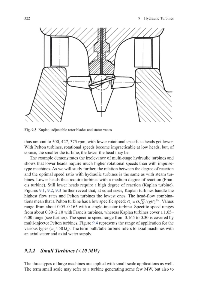
Figures 9.1, 9.2, 9.3 further reveal that, at equal sizes, Kaplan turbines handle the
highest flow rates and Pelton turbines the lowest ones. The head-flow combinations mean that a Pelton turbine has a low specific speed: Ω Ω
s
Q gH
=
/ ( ) .
/
3 4
Values
range from about 0.05–0.165 with a single-injector turbine. Specific speed ranges
from about 0.30–2.10 with Francis turbines, whereas Kaplan turbines cover a 1.65–
6.00 range (see further). The specific speed range from 0.165 to 0.30 is covered by
multi-injector Pelton turbines. Figure 9.4 represents the range of application for the
various types ( n q ≈ 50 Ω s ). The term bulb/tube turbine refers to axial machines with
an axial stator and axial water supply.
9.2.2 Small Turbines (< 10 MW)
The three types of large machines are applied with small-scale applications as well.
The term small scale may refer to a turbine generating some few MW, but also to
Fig. 9.3 Kaplan; adjustable rotor blades and stator vanes
322
thus amount to 500, 427, 375 rpm, with lower rotational speeds as heads get lower.
With Pelton turbines, rotational speeds become impracticable at low heads, but, of
course, the smaller the turbine, the lower the head may be.
The example demonstrates the irrelevance of multi-stage hydraulic turbines and
shows that lower heads require much higher rotational speeds than with impulsetype machines. As we will study further, the relation between the degree of reaction
and the optimal speed ratio with hydraulic turbines is the same as with steam turbines. Lower heads thus require turbines with a medium degree of reaction (Francis turbine). Still lower heads require a high degree of reaction (Kaplan turbine).
Figures 9.1, 9.2, 9.3 further reveal that, at equal sizes, Kaplan turbines handle the
highest flow rates and Pelton turbines the lowest ones. The head-flow combinations mean that a Pelton turbine has a low specific speed: Ω Ω
s
Q gH
=
/ ( ) .
/
3 4
Values
range from about 0.05–0.165 with a single-injector turbine. Specific speed ranges
from about 0.30–2.10 with Francis turbines, whereas Kaplan turbines cover a 1.65–
6.00 range (see further). The specific speed range from 0.165 to 0.30 is covered by
multi-injector Pelton turbines. Figure 9.4 represents the range of application for the
various types ( n q ≈ 50 Ω s ). The term bulb/tube turbine refers to axial machines with
an axial stator and axial water supply.
9.2.2 Small Turbines (< 10 MW)
The three types of large machines are applied with small-scale applications as well.
The term small scale may refer to a turbine generating some few MW, but also to
Fig. 9.3 Kaplan; adjustable rotor blades and stator vanes