

9.2 Hydraulic Turbine Types
323
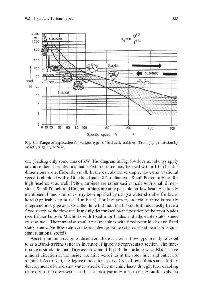
one yielding only some tens of kW. The diagram in Fig. 9.4 does not always apply
anymore then. It is obvious that a Pelton turbine may be used with a 10 m head if
dimensions are sufficiently small. In the calculation example, the same rotational
speed is obtained with a 10 m head and a 0.2 m diameter. Small Pelton turbines for
high head exist as well. Pelton turbines are rather easily made with small dimensions. Small Francis and Kaplan turbines are only possible for low head. As already
mentioned, Francis turbines may be simplified by using a water chamber for lower
head (applicable up to a 4–5 m head). For low power, an axial turbine is mostly
integrated in a pipe as a so-called tube turbine. Small axial turbines mostly have a
fixed stator, as the flow rate is mainly determined by the position of the rotor blades
(see further below). Machines with fixed rotor blades and adjustable stator vanes
exist as well. There are also small axial machines with fixed rotor blades and fixed
stator vanes. No flow rate variation is then possible (at a constant head and a constant rotational speed).
Apart from the three types discussed, there is a cross-flow type, mostly referred
to as a Banki-turbine (after its inventor). Figure 9.5 represents a section. The functioning is similar to that of a cross-flow fan (Chap. 3), but turbine-wise. Blades have
a radial direction at the inside. Relative velocities at the rotor inlet and outlet are
identical. As a result, the degree of reaction is zero. Cross-flow turbines are a further
development of undershot water wheels. The machine has a draught tube enabling
recovery of the downward head. The rotor partially runs in air. A sniffer valve is
Fig. 9.4 Range of application for various types of hydraulic turbines. (From [1]; permission by
Vogel Verlag); n q
s
≈ 50Ω
323
one yielding only some tens of kW. The diagram in Fig. 9.4 does not always apply
anymore then. It is obvious that a Pelton turbine may be used with a 10 m head if
dimensions are sufficiently small. In the calculation example, the same rotational
speed is obtained with a 10 m head and a 0.2 m diameter. Small Pelton turbines for
high head exist as well. Pelton turbines are rather easily made with small dimensions. Small Francis and Kaplan turbines are only possible for low head. As already
mentioned, Francis turbines may be simplified by using a water chamber for lower
head (applicable up to a 4–5 m head). For low power, an axial turbine is mostly
integrated in a pipe as a so-called tube turbine. Small axial turbines mostly have a
fixed stator, as the flow rate is mainly determined by the position of the rotor blades
(see further below). Machines with fixed rotor blades and adjustable stator vanes
exist as well. There are also small axial machines with fixed rotor blades and fixed
stator vanes. No flow rate variation is then possible (at a constant head and a constant rotational speed).
Apart from the three types discussed, there is a cross-flow type, mostly referred
to as a Banki-turbine (after its inventor). Figure 9.5 represents a section. The functioning is similar to that of a cross-flow fan (Chap. 3), but turbine-wise. Blades have
a radial direction at the inside. Relative velocities at the rotor inlet and outlet are
identical. As a result, the degree of reaction is zero. Cross-flow turbines are a further
development of undershot water wheels. The machine has a draught tube enabling
recovery of the downward head. The rotor partially runs in air. A sniffer valve is
Fig. 9.4 Range of application for various types of hydraulic turbines. (From [1]; permission by
Vogel Verlag); n q
s
≈ 50Ω